Hyundai Elantra (CN7): Engine Mechanical System / Repair procedures
| Compession Pressure Inspection |
|

| 1. | Start the engine and turn the coolant temperature to 80 - 95 °C and stop. |
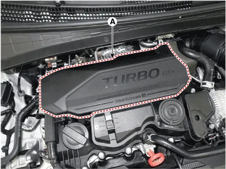
| 2. | Remove the engine cover (A).
|
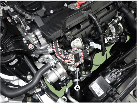
| 3. | Disconnect the injector connector (A).
|
| 4. | Remove the ignition coils. (Refer to Engine Electical System - "Ignition Coil") |
| 5. | Remove spark plugs. (Refer to Engine Electrical System - "Spark Plug") |
| 6. | Check the cylinder compression pressure.
|

| 7. | Install the spark plugs. (Refer to Engine Electrical System - "Spark Plug") |
| 8. | Install the ignition coil. (Refer to Engine Electical System - "Ignition Coil") |
| 9. | Connect the injector connector (A).
|
| 10. | Some DTCs may exist after the inspection test and may need to be manually cleared with diagnostic tool. |
| 11. | Install the engine cover. (Refer to Engine and Transaxle Assembly - "Engine Cover") |
Specifications Description Specifications Limit General TypeIn-line, DOHC  Number of cylinders4  Bore75.
Troubleshooting Symptom Suspect area Remedy Engine misfire with abnormal internal lower engine noises.
Other information:
Hyundai Elantra (CN7) 2021-2026 Service Manual: Troubleshooting
TroubleshootingProblem Symptoms TableBefore replacing or repairing air conditioning components, first determine if the malfunction is due to the refrigerant charge, air flow or compressor.Use the table below to help you find the cause of the problem. The numbers indicate the priority of the likely cause of the problem.
Hyundai Elantra (CN7) 2021-2026 Service Manual: Heater Core
Repair procedures Replacement1.Disconnect the negative (-) battery terminal. 2.Remove the heater and blower assembly.(Refer to Heater - "Heater Unit") 3.Remove the heater core cover (A) after loosening the mounting screws.4.Pull out the heater core (A) from the heater unit.
Categories
- Manuals Home
- Hyundai Elantra Owners Manual
- Hyundai Elantra Service Manual
- Body Electrical System
- Front Radar Unit
- Vehicle Information
- New on site
- Most important about car
