Hyundai Elantra: Front Axle Assembly. Front Hub / Knuckle / Tone Wheel / Repair procedures
| Removal |
| 1. | Loosen the wheel nuts slightly. Raise the vehicle, and make sure it is securely supported. |
| 2. | Remove the front wheel and tire (A) from the front hub.
|

| 3. | Remove the front brake caliper. (Refer to Brake System - "Front Disc Brake") |
| 4. | Loosen the screw and the remove the front disc (A).
|
| 5. | By hammering on a chisel, unlock the driveshaft lock hub nut caulking.
|
| 6. | Loosen the driveshaft caulking nut (A) from the front hub.
|
| 7. | Loosen the mounting bolts from the knuckle and then remove the hub bearing assembly and dust cover (A) by using the plastic hammer.
|
| 8. | Remove the tie rod end ball joint by using the special service tool.
|
| 9. | Remove the wheel speed sensor (A) from the knuckle after loosening the mounting bolt.
|
| 10. | Separate the lower arm ball joint by using the SST (09568-1S100) after loosening the lower arm mounting nut (A).
|
| 11. | Remove the front knuckle (A) after loosening the bolts and nuts.
|
| Inspection |
| 1. | Check the hub for cracks and the splines for wear. |
| 2. | Check the brake disc for scoring and damage. |
| 3. | Check the knuckle for cracks. |
| 4. | Check the bearing for cracks or damage. |
| Installation |
| 1. | To install, reverse the removal procedures. |
| 2. | Check the alignment. (Refer to Suspension System - "Alingment") |


Other information:
Hyundai Elantra (CN7) 2021-2025 Service Manual: Oil Pump
Repair procedures Removal and InstallationOil Pump1.Remove the engine room under cover.(Refer to Engine and Transaxle Assembly - "Engine Room Under Cover")2.Drain the engine oil.(Refer to Lubrication System - "Engine Oil")3.Remove the oil pan.(Refer to Lubrication System - "Oil Pan")4.Turn the oil pump chain tensioner (A) in the direction of the arrow and remove the oil pump chain (B) from the ..
Hyundai Elantra (CN7) 2021-2025 Owner's Manual: System operation
To set speed limit 1. Press and hold Driving Assist () button at the desired speed. The Manual Speed Limit Assist enabled () indicator will illuminate on the cluster. 2. Push the + switch up or - switch down, and release it at the desired speed. Push the + switch up or - switch down and hold it. The speed will increase or decrease to the nearest multiple of ten (multiple of five in mph)..
Categories
- Manuals Home
- 7th Gen Hyundai Elantra Owners Manual
- 7nd Gen Hyundai Elantra Service Manual
- Vehicle Information
- System operation
- Control Cable
- Interior Overview
- Fuel gauge
Odometer
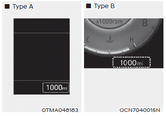
The odometer indicates the total distance that the vehicle has been driven and should be used to determine when periodic maintenance should be performed.

Copyright © 2025 www.helantra7.com