Hyundai Elantra (CN7): Emission Control System / Schematic diagrams
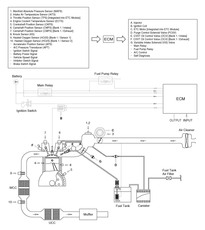
| Schematic Diagram |
SpecificationsPurge Control Solenoid Valve (PCSV)▷ Specification Item Specification Coil Resistance (Ω)22.
Schematic diagrams Schematic Diagram1. Air cleaner2. Delivery pipe & injector3. Engine4. Purge control solenoid valve (PCSV)5. Fuel tank air filter6.
Other information:
Hyundai Elantra (CN7) 2021-2026 Service Manual: Repair procedures
Diagnosis with Diagnostic tool1.In the body electrical system, failure can be quickly diagnosed by using the vehicle diagnostic system (Diagnostic tool).The diagnostic system (Diagnostic tool) provides the following information.(1)Fault Code Searching : Checking failure and code number (DTC)(2)Data Analysis : Checking the system input/output data s
Hyundai Elantra (CN7) 2021-2026 Service Manual: Evaporator Temperature Sensor
Description and operation DescriptionThe evaporator temperature sensor will detect the evaporator core temperature and interrupt compressor relay power in order to prevent evaporator from freezing by excessive cooling. The evaporator temperature sensor has the Negative Temperature Coefficient (NTC).
Categories
- Manuals Home
- Hyundai Elantra Owners Manual
- Hyundai Elantra Service Manual
- Integrated Thermal Management Module (ITM)
- Troubleshooting
- Front Bumper
- New on site
- Most important about car
