Hyundai Elantra (CN7): Motor Driven Power Steering / Schematic diagrams
| Schematic Diagrams |
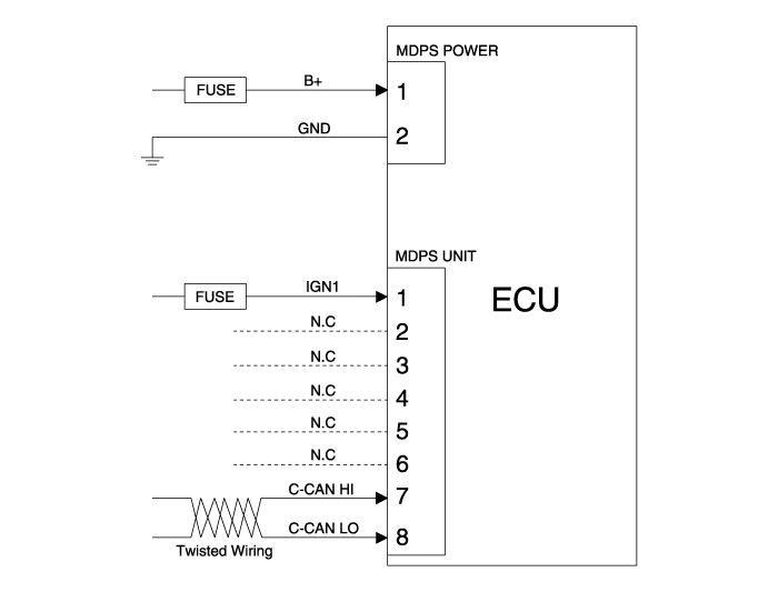
| Terminal function |
|
Type
|
Pin No
|
Description
|
| Battery | 1 | Battery + |
| 2 | Battery - | |
| VSS | 1 | IGN |
| 2 | - | |
| 3 | - | |
| 4 | - | |
| 5 | - | |
| 6 | - | |
| 7 | HIGH CAN | |
| 8 | LOW CAN |
Components 1. Steering wheel2. Steering column3. MDPS power pack4. Universal joint5. Dust cap6. Tie rod end7. Bellows8. Steering gear box
A/S Repair produresMDPS System A/S Workflow ※ For detailed DTC or other DTC A/S procedures, see "CN7 MDPS DTC Diagnostic Guide" ① Noise / malfunction Inspection② Warning lamp (DTC) / CAN Line error2 - 1 Checking Connectors and Wiring1.
Other information:
Hyundai Elantra (CN7) 2021-2025 Service Manual: Heater Control Unit
Components and components location Component Location1. Heater control unitComponents[Connector A] Pin No Function Pin No Function 1Mode control actuator (Feedback)21Mode control actuator (Vent)2Intake actuator (Feedback)22Mode control actu
Hyundai Elantra (CN7) 2021-2025 Service Manual: Warning Indicator
Components and components location Components1. BSD Indicator2. Side repeater lamp Repair procedures Inspection1.Disconnect the negative (-) battery terminal.2.Remove the front door trim.(Refer to Body - "Front door trim")3.Disconnect the power door mirror connector from the harness4.
Categories
- Manuals Home
- Hyundai Elantra Owners Manual
- Hyundai Elantra Service Manual
- Front Bumper
- Engine Mechanical System
- Instrument Cluster
- New on site
- Most important about car