Hyundai Elantra (CN7): Seat Electrical / Seat Heater
Components and components location
| Component Location |
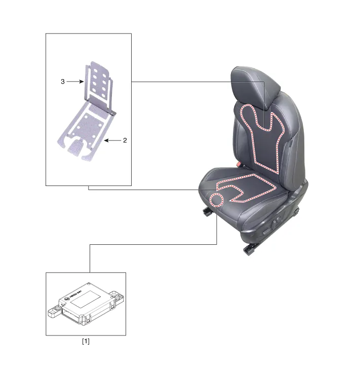
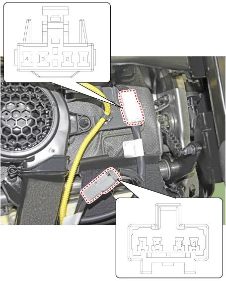
| 1. Seat heater unit (Passenger only) 2. Seat cushion heater | 3. Seat back heater |
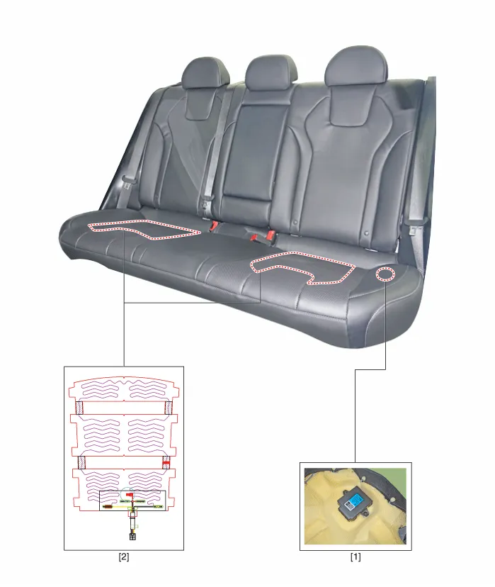
| 1. Seat heater unit | 2. Seat cushion heater |
Schematic diagrams
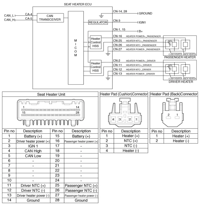
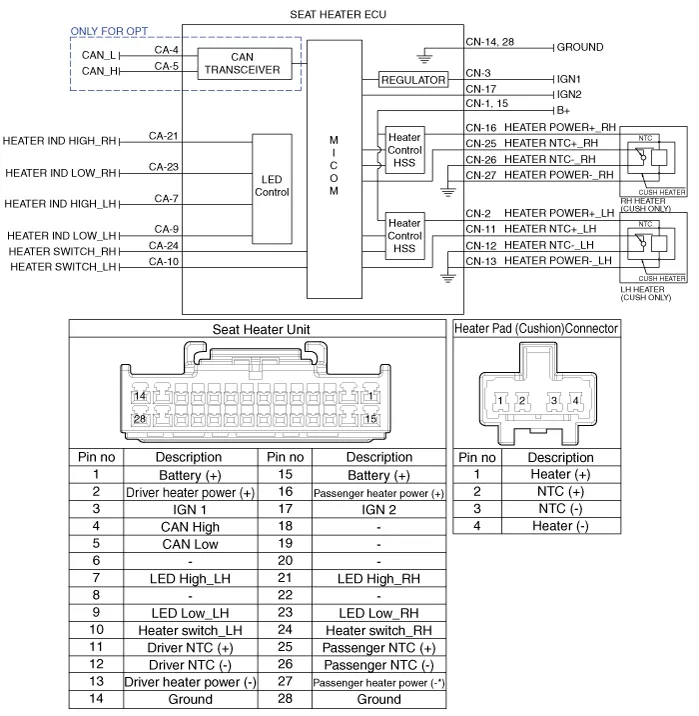
| Circuit Diagram |
Repair procedures
| Inspection |
| 1. | Check for continuity and measure the resistance between terminals No 3 and No 6.
|
| 2. | Operate the seat heater after connecting the connector, and then check the thermostat by measuring the temperature of seat surface.
|
| 1. | Check for continuity and measure the resistance between terminals No 1 and No 4.
|
| 2. | Operate the seat heater after connecting the connector, and then check the thermostat by measuring the temperature of seat surface.
|
| 1. | You can enter the diagnosis mode by turning the seat heater button on. |
| 2. | You can enter the diagnosis mode by referring to following description.
|
| 3. | After entering the diagnosis mode, you can check what failed by checking the blinking LED. [Driver / Passenger Seat Heater]
[Rear Seat He7ater]
|
| 4. | You can check the malfunctioning by checking the blinking LED. |
| 5. | Pressing the IGN OFF button will end the diagnosis mode for the heater seat. |
| 6. | You can check whether the heating seat system works properly after turning the IGN ON. If you want to check the error code, you can refer to the procedure of 2 above. |
Repair procedures Removal1.Disconnect the negative (-) battery terminal.2.Remove the front seat outer shield cover.(Refer to Body - "Front Seat Outer Shield Cover")3.
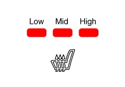
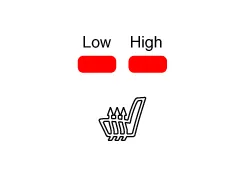
Components and components location Components1. Driver seat heater switch2. Passenger seat heater swtich3. 2nd seat heater switch Schematic diagrams Circuit DiagramManual Seat Heater SwitchConnector Pin Information[Connector A] Pin No Function Pin No Function 1Low (Register specifications)4Middle Low (Register specifications)2Common (Register specifications)5Middle High (Register specifications)3Ground (Register specifications)6High (Register specifications)[Connector B] Pin No Function Pin No Function 1Battery (+)21IGN22ISG B+22IGN13ILL+ (TAIL)23Blower IS (PWM specifications)4Sensor REF (+5V)24-5Mode control actuator (Feedback)25-6Temperature control actuator (Feedback)26-7Intake actuator (Feedback)27Blower Max.
Other information:
Hyundai Elantra (CN7) 2021-2025 Service Manual: Blower Resistor (Manual)
Repair procedures Inspection1.Measure the resistance between the terminals.2.The measured resistance is not within specification, the blower resistor must be replaced. (After removing the resistor)Replacement1.Disconnect the negative (-) battery terminal.
Hyundai Elantra (CN7) 2021-2025 Service Manual: Rear Corner Radar Unit
Specifications Specifications Items Blind-Spot Collision Warning (BCW) Blind-Spot Collision- Avoidance Assist-Rear (BCA-R) Rated voltageDC 12VOperating voltage9V - 16VOperating speed30 km/h - 255 km/h60 km/h - 180 km/hSensible distance70m Curvature radiusStart : More
Categories
- Manuals Home
- Hyundai Elantra Owners Manual
- Hyundai Elantra Service Manual
- Clutch System
- Drive Mode
- Body Electrical System
- New on site
- Most important about car
