Hyundai Elantra: Smart Key System / Smart key antenna
Hyundai Elantra (CN7) 2021-2025 Service Manual / Body Electrical System / Smart Key System / Smart key antenna
Repair procedures
| Removal |
Interior 1 Antenna
|

| 1. | Disconnect the negative (-) battery terminal. |
| 2. | Remove the console assembly. (Refer to Body - "Floor Console Assembly") |
| 3. | Remove the interior 1 antenna (B) after loosening the mounting nuts and disconnecting the connector (A).
|
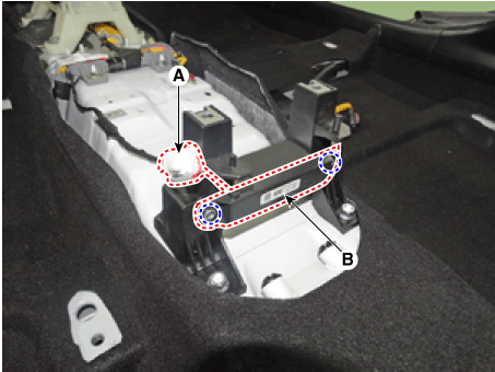
Interior 2 Antenna
| 1. | Disconnect the negative (-) battery terminal. |
| 2. | Remove the console rear complete assembly. (Refer to Body - "Floor Console Assembly") |
| 3. | Remove the interior 1 antenna (B) after loosening the mounting nuts (2EA) and disconnecting the connector (A).
|
Interior 3 Antenna
| 1. | Disconnect the negative (-) battery terminal. |
| 2. | Remove the rear transverse trim (A).
|
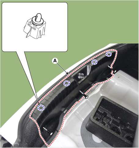
| 3. | Remove the interior 3 antenna (B) after loosening mounting screws and disconnecting the connector (A).
|
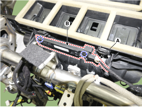
Exterior Bumper Antenna
| 1. | Disconnect the negative (-) battery terminal. |
| 2. | Remove the rear bumper. (Refer to Body - "Rear Bumper Assembly") |
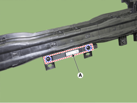
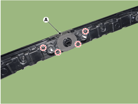
| 3. | Rremove the exterior bumper antenna (A) after loosening mounting nuts.
|
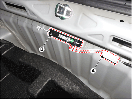
Front Door Antenna
| 1. | Disconnect the negative (-) battery terminal. |
| 2. | Remove the front door trim. (Refer to Body - "Front Door Trim") |
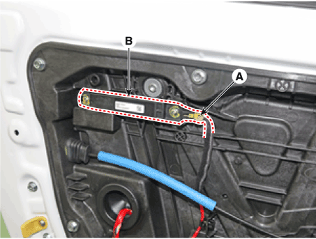
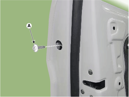
| 3. | Remove the front door antenna (B) after loosening mounting screws and disconnecting the connector (A).
|
Buzzer
| 1. | Disconnect the negative (-) battery terminal. |
| 2. | Remove the front left wheel guard. |
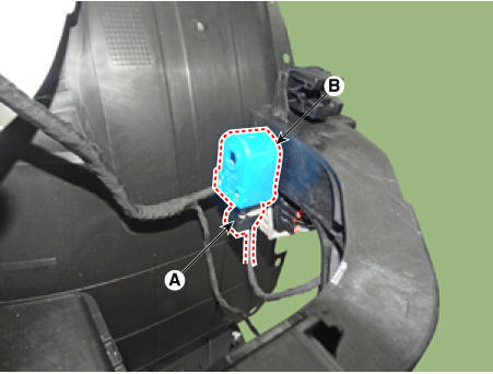
| 3. | Disconnect the connectors (A), then remove the buzzer (A).
|
Door Outside Handle
| 1. | Disconnect the negative (-) battery terminal. |
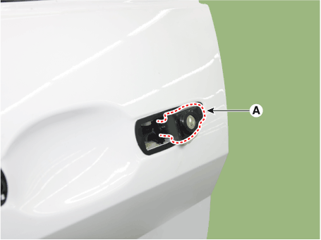
| 2. | Loosen the mounting bolt after remove the plug hall (A). And then push the outside handle in the direction of arrow as illustration below.
|
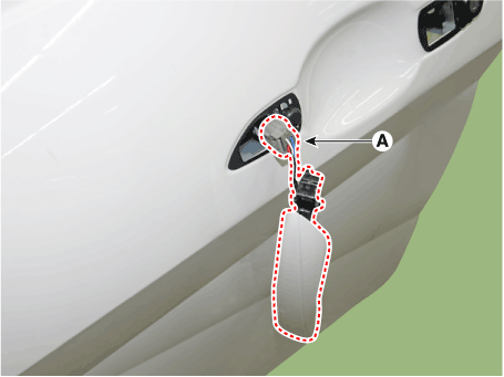
| 3. | Loosen the mounting screw (A) and then remove the front door outside handle (B) by sliding it forward.
|

| 4. | Remove the front door lock assembly (A).
|
| 5. | Disconnect the front door outside handle connector (A).
|
Trunk Open Switch
| 1. | Disconnect the negative (-) battery terminal. |
| 2. | Remove the inside rear combination lamp (A). (Refer to Lighting System - "Rear Combination Lmap") |
| 3. | Remove the trunk rid open switch assembly (A).
|
| Installation |
Interior 1 Antenna
| 1. | Install the interior 1 antenna. |
| 2. | Install the floor console assembly. |
| 3. | Install the negative (-) battery terminal and check the smart key system. |
Interior 2 Antenna
| 1. | Install the interior 2 antenna. |
| 2. | Install the console rear complete assembly. |
| 3. | Install the negative (-) battery terminal and check the smart key system. |
Interior 3 Antenna
| 1. | Install the interior 3 antenna. |
| 2. | Install the rear transverse trim. |
| 3. | Install the negative (-) battery terminal and check the smart key system. |
Exterior Bumper Antenna
| 1. | Install the exterior bumper antenna. |
| 2. | Install the rear bumper cover. |
| 3. | Install the negative (-) battery terminal and check the smart key system. |
Front Antenna
| 1. | Install the exterior bumper antenna. |
| 2. | Install the front bumper cover. |
| 3. | Install the negative (-) battery terminal and check the smart key system. |
Front Door Antenna
| 1. | Install the front door antenna. |
| 2. | Install the front door trim. |
| 3. | Install the negative (-) battery terminal and check the smart key system. |
Buzzer
| 1. | Install the buzzer. |
| 2. | Install the front left wheel guard. |
| 3. | Install the negative (-) battery terminal and check the smart key system. |
Door Outside Handle
| 1. | Install the outside handle. |
| 2. | Install the door trim. |
| 3. | Install the negative (-) battery terminal and check the smart key system. |
Trunk rid open switch
| 1. | Install the Trunk rid open switch. |
| 2. | Install the inside rear combination lamp. |
| 3. | Install the negative (-) battery terminal and check the smart key system. |
 Smart Key Diagnostic
Repair procedures
InspectionSelf Diagnosis With Scan ToolIt will be able to diagnose defects of SMART KEY system with Diagnostic tool quickly. Diagnostic tool can operates actuator forcefully, input/output value monitoring and self diagnosis...

Other information:
Hyundai Elantra (CN7) 2021-2025 Owner's Manual: Side air bags
Front seat Your vehicle is equipped with a side air bag in each front seat. The purpose of the air bag is to provide the vehicle’s driver and the front passenger with additional protection than that offered by the seat belt alone. The side air bags are designed to deploy only during certain side impact collisions, depending on the crash severity. The side and curtain air bags on both s..
Hyundai Elantra (CN7) 2021-2025 Owner's Manual: How to deactivate the Smart Trunk release function using the smart key
1. Door lock 2. Door unlock 3. Trunk open 4. Panic 5. Remote Start If you press any button of the smart key during the Detect and Alert stage, the Smart Trunk release function will be deactivated. Make sure to be aware of how to deactivate the Smart Trunk release function for emergency situations. Information If you press the door unlock button (2), the Smart Trunk release function ..
Categories
- Manuals Home
- 7th Gen Hyundai Elantra Owners Manual
- 7nd Gen Hyundai Elantra Service Manual
- Vehicle Information
- Body Electrical System
- Interior Overview
- Drive Mode
- System disabled
Tachometer
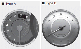
The tachometer indicates the approximate number of engine revolutions per minute (RPM).
Use the tachometer to select the correct shift points and to prevent lugging and/ or over-revving the engine.
NOTICE
Do not operate the engine within the tachometer's RED ZONE. This may cause severe engine damage.

Copyright © 2025 www.helantra7.com