Hyundai Elantra (CN7): Audio / Speakers
Repair procedures
| Inspection |
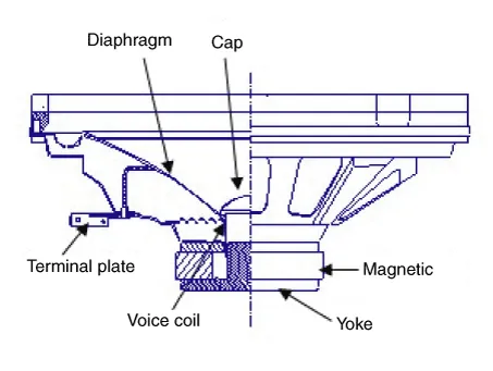
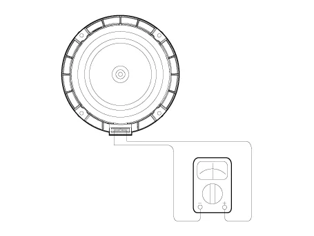
| 1. | Troubleshooting for Speaker
|


| Removal |
| 1. | Disconnect the negative (-) battery terminal. |
| 2. | Remove the front door trim. (Refer to Body - "Front Door Trim") |
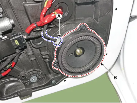
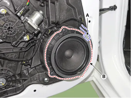
| 3. | Remove the front door speaker (B) after disconnecting the connector (A) and loosening screws.
|
| 1. | Disconnect the negative (-) battery terminal. |
| 2. | Remove the front door trim. (Refer to Body - "Front Door Trim") |
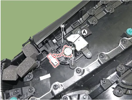
| 3. | Remove the tweeter speaker (A) after loosening screws.
|
| 1. | Disconnect the negative (-) battery terminal. |
| 2. | Remove the rear door trim. (Refer to Body - "Rear Door Trim") |
| 3. | Remove the rear door speaker (B) after disconnecting the connector (A) and loosening screws.
|
| Installation |
| 1. | Install the front door speaker. |
| 2. | Install the front door trim. |
| 3. | Connect the negative (-) battery terminal. |
| 1. | Install the front door tweeter speaker. |
| 2. | Install the front door trim. |
| 3. | Connect the negative (-) battery terminal. |
| 1. | Install the rear door speaker. |
| 2. | Install the front door trim. |
| 3. | Connect the negative (-) battery terminal. |
|
Components and components location ComponentsAudioConnector Pin Information No Connector A Connector B 1Rear left speaker (+)MM_CAN High2Front left speaker (+)-3Front right speaker (+)-4Rear right speaker (+)Steering wheel remote5--6Door openUSB DATA (+)7IGN1USB VOC8Illumination (+)-9Detent-10Rear left speaker (-)Mic (+) 11Front left speaker (-)ACC12Front right speaker (-)B+13Rear right speaker (-)MM_CAN Low14--15--16-Vehicle Speed17Illumination (-)Steering wheel remote GND18-USB DATA (-)19USB GND20-21-22Mic (-) 23-24GND[Display Audio]Connector Pin Information No Connector A (Int AMP) Connector A (Ext AMP) Connector B 1Rear left speaker (+)--2Reart left speaker (-)-MIC Signal (+)3-AMP Navi Voice (+)-4-AMP SPDIF (HI)-5--Antenna Powr6Camera PowerCamera PowerILL (+)7Camera VideoCamera VideoMM CAN (HI)8---9---10--B+11--B+12Steering wheel remote Steering wheel remote GND13Front lift speaker (+)-GND14Front lift speaker (-)-MIC GND15Front right speaker (-)-MIC Signal (-)16Front right speaker (+)--17-AMP Navi Voice (-)-18-AMP SPDIF (LOW)-19-AMP SPDIF GND-20Camera Power GNDCamera Power GNDMM CAN (LOW)21Camera Video GNDCamera Video GND-22--ACC23---24---25---26Steering wheel remote GNDSteering wheel remote GND-27Rear right speaker (-)--28Rear right speaker (+)--29---30---31---32---33--IGN 134---35---36--37--38SpeedSpeed Repair procedures Removal • Take care not to scratch the cluster fascia panel and related parts.
Repair procedures InspectionGlass Antenna Test1.Wrap aluminum foil (A) around the tip of the tester probe (B) as shown.2.Touch one tester probe to the glass antenna terminal (A) and move the other tester probe along the antenna wires to check that continuity exists.
Other information:
Hyundai Elantra (CN7) 2021-2026 Service Manual: Head Lamp Leveling Device
Components and components location Component Location1. Head lamp leveling actuator2. Head lamp leveling switch Head Lamp Leveling Switch Schematic diagrams Schematic Diagrams Repair procedures Replacement1.Disconnect the negative (-) battery terminal.
Hyundai Elantra (CN7) 2021-2026 Service Manual: Wireless Charging Lamp
Components and positions Components Repair procedures Removal • Handling wireless charging system parts by wet hands may cause electric shock. 1.Disconnect the negative (-) battery terminal.2.Remove the floor console upper cover assembly.
Categories
- Manuals Home
- Hyundai Elantra Owners Manual
- Hyundai Elantra Service Manual
- Recommended Lubricants and Capacities
- Integrated Thermal Management Module (ITM)
- General Tightening Torque Table. General information
- New on site
- Most important about car
