Hyundai Elantra: Heater / Temperature Control Actuator
Hyundai Elantra (CN7) 2021-2025 Service Manual / Heating, Ventilation and Air Conditioning / Heater / Temperature Control Actuator
Description and operation
| Description |
The temperature control actuator is located at the heater unit. It regulates the temperature by the procedure as follows.
The signal from the control unit adjusts the position of the temperature door by operating the temperature switch. Then the temperature will be regulated by the hot/cold air ratio decided by the position of the temperature door.
Components and components location
| Components Location |
| 1. Temperature control actuator [LH] | 2.Temperature control actuator [RH] |
Specifications
| Specifications |
|
Door Position
|
Voltage (V)
|
Error Detecting
|
| Max. cooling | 0.3 ± 0.15 | Low voltage : 0.1V or less High voltage : 4.9V or more |
| Max. heating | 4.7 ± 0.15 |
Repair procedures
| Inspection |
| 1. | Turn the ignition switch OFF. |
| 2. | Disconnect the temperature control actuator connector. |
| 3. | Verify that the temperature control actuator operates to the cool position when connecting 12V to terminal 3 and grounding terminal 7. Verify that the temperature control actuator operates to the warm position when connected in reverse.
|
| 4. | Connect the temperature control actuator connector. |
| 5. | Turn the ignition switch ON. |
| 6. | Check the voltage between terminal 5 and 6. |
| 7. | If the measured voltage is not within specification, check the operation by replacing the existing temperature control actuator with a new genuine part. After that, determine whether replacement of the temperature control actuator is required or not. |
| Replacement |
[Driver's side]
| 1. | Disconnect the negative (-) battery terminal. |
| 2. | Remove the crash pad lower panel. (Refer to Body (Interior and Exterior) - "Crash Pad Lower Panel") |
| 3. | Loosen the mounting screw, remove the shower duct (A).
|
| 4. | Disconnect the connector (A) and then remove the driver's side temperature control actuator (B) after loosening the mounting screws.
|
| 5. | To install, reverse the removal procedure. |
[Passenger's side]
| 1. | Disconnect the negative (-) battery terminal. |
| 2. | Remove the glove box housing cover. (Refer to Body (Interior and Exterior) - "Glove Box Housing Cover") |
| 3. | Loosen the mounting screw, remove the shower duct (A).
|
| 4. | Disconnect the connector (A) and then remove the passenger's side temperature control actuator (B) after loosening the mounting screws.
|
| 5. | To install, reverse the removal procedure. |
 Evaporator Core
Repair procedures
Replacement1.Disconnect the negative (-) battery terminal. 2.Remove the heater and blower assembly.(Refer to Heater - "Heater Unit") 3...
 Mode Control Actuator
Description and operation
DescriptionThe mode control actuator is located at the heater unit.It adjusts the position of the mode door by operating the mode control actuator based on the signal of the A/C control unit...
Other information:
Hyundai Elantra (CN7) 2021-2025 Service Manual: Front Lower Arm
Repair procedures Removal1.Loosen the wheel nuts slightly.Raise the vehicle, and make sure it is securely supported.2.Remove the front wheel and tire (A) from the front hub. Tightening torque : 107.9 - 127.5 N.m (11.0 - 13.0 kgf...
Hyundai Elantra (CN7) 2021-2025 Owner's Manual: Check Tire Inflation Pressure
Check your tires, including the spare tire, once a month or more. How to check Use a good quality tire pressure gauge to check tire pressure. You can not tell if your tires are properly inflated simply by looking at them. Radial tires may look properly inflated when they are underinflated...
Categories
- Manuals Home
- 7th Gen Hyundai Elantra Owners Manual
- 7nd Gen Hyundai Elantra Service Manual
- Integrated Thermal Management Module (ITM)
- Rear Seats
- System disabled
- Body Electrical System
- Dimensions, Engine specification, Bulb Wattage
Odometer
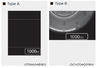
The odometer indicates the total distance that the vehicle has been driven and should be used to determine when periodic maintenance should be performed.

Copyright © 2025 www.helantra7.com