Hyundai Elantra (CN7): Timing System / Timing Chain Cover
Hyundai Elantra (CN7) 2021-2026 Service Manual / Engine Mechanical System / Timing System / Timing Chain Cover
Repair procedures
| Removal |
|

|

| 1. | Disconnect the battery negative terminal. |
| 2. | Remove the engine cover. (Refer to Engine and Transaxle Assembly - "Engine Cover") |
| 3. | Remove the engine room under cover. (Refer to Engine And Transaxle Assembly - "Engine Room Under Cover") |
| 4. | Drain the engine coolant. (Refer to Cooling System - "Coolant") |
| 5. | Drain the engine oil. (Refer to Lubrication System - "Engine Oil") |
| 6. | Remove the drive belt. (Refer to Drive Belt System - "Drive Belt") |
| 7. | Remove the drive belt tensioner. (Refer to Drive Belt System - "Drive Belt Tensioner") |
| 8. | Remove the alternator. (Refer to Engine Electrical System - "Alternator") |
| 9. | Remove the crankshaft damper pulley. (Refer to Drive Belt System - "Crankshaft Damper Pulley") |
| 10. | Remove the cylinder head cover. (Refer to Cylinder Head Assembly - "Cylinder Head Cover") |
| 11. | Remove the water pump. (Refer to Cooling System - "Water Pump") |
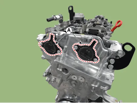
| 12. | Remove the intake and exhaust variable force solenoid (VFS) valves (A).
|
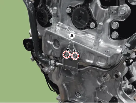
| 13. | Remove the turbo charger coolant hose and pipe mounting bolts (A).
|
| 14. | Remove the oil pan. (Refer to Lubrication System - "Oil Pan") |
| 15. | Insert the rubber block between jack and lower crankcase. |
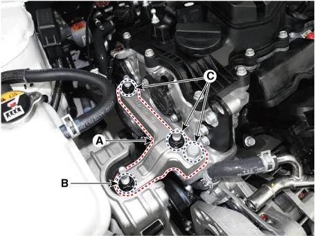
| 16. | Remove the engine mounting support bracket (A).
|
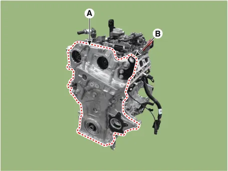
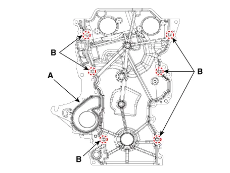
| 17. | Remove the timing chain cover (A) and hanger (B).
|
| Installation |
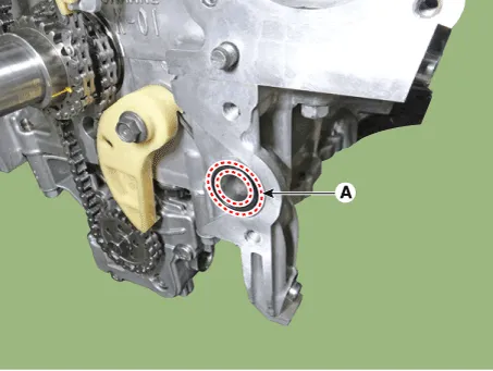
| 1. | Install the new O-ring (A).
|
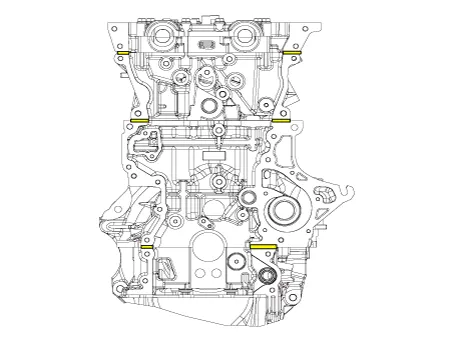
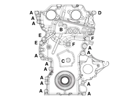
| 2. | Install the timing chain cover.
|
| 3. | Replace the front oil seal. (Refer to Timing System - "Front Oil Seal") |
| 4. | Install the other parts in the reverse order of removal. |
| 5. | Refill engine with engine oil. (Refer to Lubrication System - "Engine Oil") |
| 6. | Fill with engine coolant. (Refer to Cooling System - "Coolant")
|
Repair procedures Replacement1.Remove the crankshaft damper pulley.(Refer to Drive Belt System - "Crankshaft Damper Pulley")2.Remove the front oil seal (A).
Components and components location Components1. Variable force solenoid valves 2. Timing chain cover3. Cam to cam guide4. Timing chain5. Timing chain tensioner arm6.
Other information:
Hyundai Elantra (CN7) 2021-2026 Service Manual: Components and components location
C
Hyundai Elantra (CN7) 2021-2026 Service Manual: Smart Cruise Control (SCC) Switch
Schematic diagrams Circuit DiagramTRIP / SCC / LFA Repair procedures Inspection1.Check for resistance between terminals in each switch position (LH).[LH : Audio + Hands free] Switch Resistance (±5%) SEEK Up430 ΩSEEK Down1.
Categories
- Manuals Home
- Hyundai Elantra Owners Manual
- Hyundai Elantra Service Manual
- Repair procedures
- Engine Control / Fuel System
- General Tightening Torque Table. General information
- New on site
- Most important about car

Copyright © 2026 www.helantra7.com - 0.0166