Hyundai Elantra (CN7): Interior Trim / Center Pillar Trim
Components and components location
| Component Location |
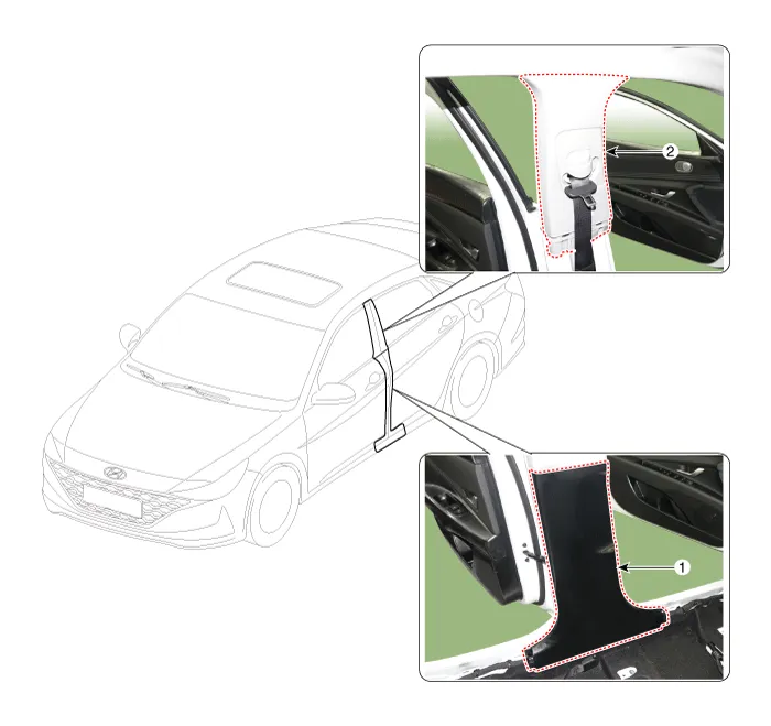
| 1. Center pillar lower trim | 2.Center pillar upper trim |
Repair procedures
| Replacement |
|

|

| 1. | Remove the front door scuff trim. (Refer to Interior Trim - "Door Scuff Trim") |
| 2. | Remove the rear door scuff trim. (Refer to Interior Trim - "Door Scuff Trim") |
| 3. | Using a screwdriver or remover, remove the center pillar lower trim (A).
|
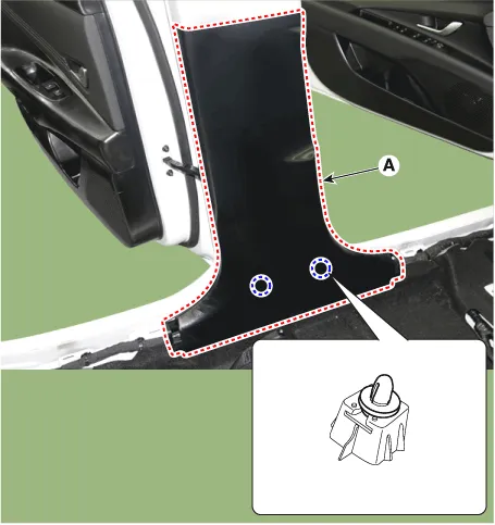
| 4. | To install, reverse the removal procedure.
|

|
|
| 1. | Remove the center pillar lower trim. (Refer to Interior Trim - "Center Pillar Trim") |
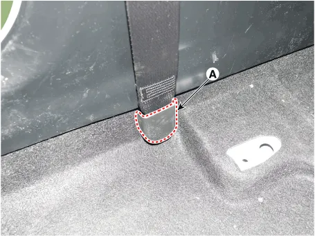
| 2. | Remove the front seat belt lower anchor cover (A).
|
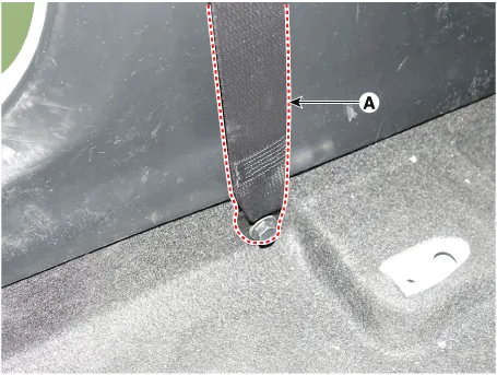
| 3. | Loosen the mounting bolt, remove the front seat belt lower anchor (A).
|
| 4. | Using a screwdriver or remover, remove the center pillar upper trim (A).
|

| 5. | To install, reverse the removal procedure.
|
Components and components location Component Location 1. Front pillar trim Repair procedures Replacement • When removing with a flat - tip screwdriver or remover, wrap protective tape around the tools to prevent damage to components.
Components and components location Component Location 1. Rear pillar trim Repair procedures Replacement • When removing with a flat - tip screwdriver or remover, wrap protective tape around the tools to prevent damage to components.
Other information:
Hyundai Elantra (CN7) 2021-2026 Service Manual: Auto Defoging Actuator
Description and operation DescriptionThe auto defogging sensor is installed on front window glass. The sensor judges and sends signal if moisture occurs to blow out wind for defogging. The air conditioner control module receives a signal from the sensor and restrains moisture and eliminates defog by the intake actuator, A/C, auto defogging actua
Hyundai Elantra (CN7) 2021-2026 Service Manual: Desctiprion and operation
DescriptionADAS_PRK is a unit that controls the functions required for ADAS parking. If the ADAS_PRK is applied, the parking distance warning function is also controlled by the ADAS_PRK.System FunctionParking Collision-Avoidance Assist (PCA)PCA is a parking safety system that assists in collision warning and emergency braking in the event of a coll
Categories
- Manuals Home
- Hyundai Elantra Owners Manual
- Hyundai Elantra Service Manual
- Front Radar Unit
- Engine Control / Fuel System
- Auto Hold. Warning messages
- New on site
- Most important about car
