Hyundai Elantra (CN7): Dual Clutch System / Dual Clutch Assembly
Components and components location
| Components |
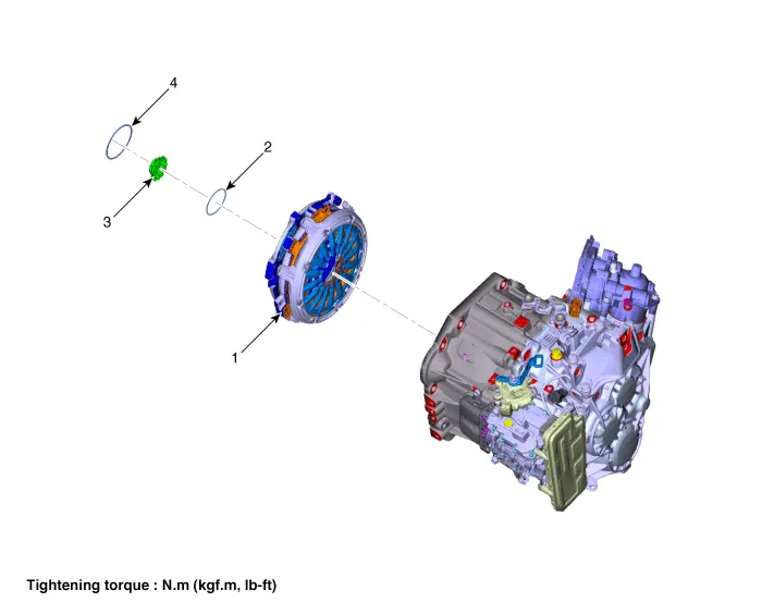
| 1. Dual clutch assembly 2. Snap ring | 3. Spline hub 4. Retaining ring |
Repair procedures
| Removal |
| 1. | Remove the dual clutch transmission from the vehicle. (Refer to Dual Clutch System - "Repair procedures") |
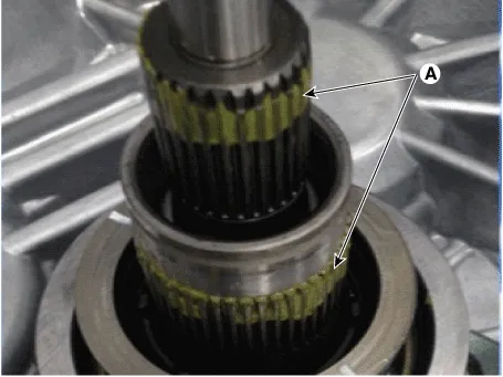
| 2. | Remove the retaining (A) and then removing the spline hub (B).
|
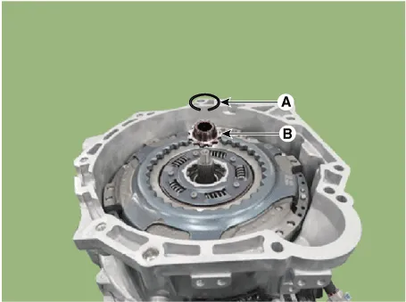
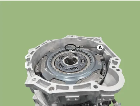
| 3. | Remove the snap ring (A).
|
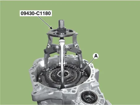
| 4. | Remove the dual clutch assembly (A) by using the special service tool [SST No.: 09430-C1180].
|
| Installation |
|

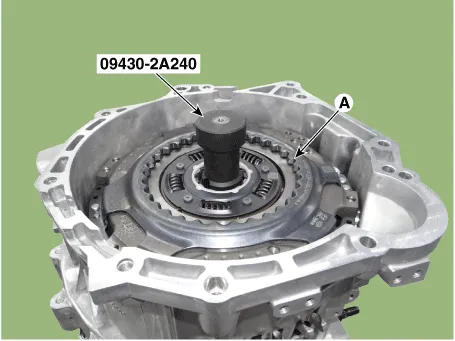
| 1. | Install the SST (No.:09430-2A240) on the support bearing within the dual clutch assembly (A).
|
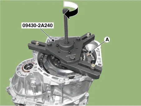
| 2. | Install the SST (No. : 09430-2A240) on the clutch housing side. |
| 3. | Install the dual clutch assembly (A) using the SST (No. : 09430-2A240).
|
| 4. | Install the snap ring (A).
|
| 5. | Install the spline hub (B) and the install the snap ring (A).
|
| 6. | Perform the work procedures for abrasion compensation reset after installing the new dual clutch assembly. (Refer to Clutch Actuator Assembly - "Adjustment") |
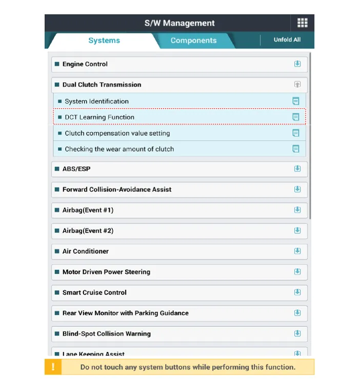
| 7. | Perform the clutch touch point learning procedure using the diagnostic tool after replacing the dual clutch assembly.
|
Description• Components location : DCT (Dual Clutch Transmission)• Function The dual clutch is installed within the transmission.
Components and components location Components1. Engagement bearing sleeve2. Clutch engagement fork3. Engagement bearing 1 (Odd)4. Engagement bearing 2 (Even)5.
Other information:
Hyundai Elantra (CN7) 2021-2026 Service Manual: Heater Core
Repair procedures Replacement1.Disconnect the negative (-) battery terminal. 2.Remove the heater and blower assembly.(Refer to Heater - "Heater Unit") 3.Remove the heater core cover (A) after loosening the mounting screws.4.Pull out the heater core (A) from the heater unit.
Hyundai Elantra (CN7) 2021-2026 Service Manual: Blower Motor
Repair procedures Inspection1.Connect the battery voltage and check the blower motor rotation.Replacement1.Disconnect the negative (-) battery terminal.2.Disconnect the blower motor connector (A) and then remove the blower motor (B) after loosening the screws.
Categories
- Manuals Home
- Hyundai Elantra Owners Manual
- Hyundai Elantra Service Manual
- Front Radar Unit
- Driver assistance system
- Specifications
- New on site
- Most important about car
