Hyundai Elantra (CN7): Emergency Call System / Emergency Call (eCall) Antenna
Hyundai Elantra (CN7) 2021-2026 Service Manual / Body Electrical System / Emergency Call System / Emergency Call (eCall) Antenna
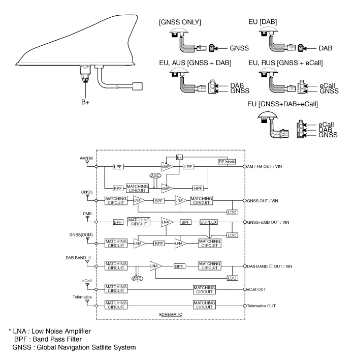
Schematic diagrams
| Components |
Repair procedures
| Removal |
Roof Antenna
| 1. | Disconnect the negative (-) battery terminal. |
| 2. | Remove the roof trim. (Refer to Body - "Roof Trim Assembly") |
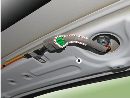
| 3. | Disconnect the roof antenna connector (A).
|
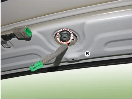
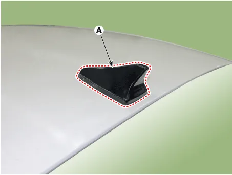
| 4. | Remove the roof antenna (A) after loosening a nut (B).
|
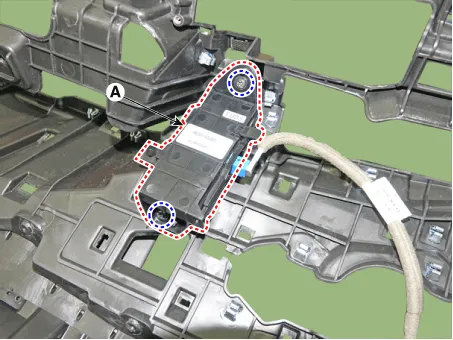
Crash Pad Antenna
| 1. | Disconnect the negative (-) battery terminal. |
| 2. | Remove the main crash pad assembly. (Refer to Body - "Main Crash Pad Assembly") |
| 3. | Loosen the mounting screws and then remove the crash pad antenna (A).
|
| Installation |
Roof Anenna
| 1. | Connect the roof antenna connectors. |
| 2. | Install the roof trim assembly.
|

Crash Pad Antenna
| 1. | Connect the roof antenna connectors and install the roof antenna. |
| 2. | Install the main crash pad assembly. |
Components and components location Component Repair procedures Removal1.Disconnect the negative (-) battery terminal.2.Using a remover and remove the overhead console (A).
Other information:
Hyundai Elantra (CN7) 2021-2026 Service Manual: High Mounted Stop Lamp
Repair procedures Removal1.Disconnect the negative (-) battery terminal.2.Remove the rear package tray trim.(Refer to Body - "Rear Package Tray Trim")3.Loosen the mounting screws and remove the high mounted stop lamp (A).Installation1.Install the high mounted stop lamp.
Hyundai Elantra (CN7) 2021-2026 Service Manual: Rear Combination Lamp
Repair procedures RemovalOutside Combination Lamp1.Disconnect the negative (-) battery terminal.2.Remove the combination lamp cover (A).3.Disconnect the rear combination lamp connector (A).4.Loosen the mounting nuts and remove the rear conbination lamp (A).
Categories
- Manuals Home
- Hyundai Elantra Owners Manual
- Hyundai Elantra Service Manual
- Specifications
- Body (Interior and Exterior)
- Front Radar Unit
- New on site
- Most important about car

Copyright © 2026 www.helantra7.com - 0.0098