Hyundai Elantra (CN7): ABS(Anti-Lock Brake System) / Rear Wheel Speed Sensor
Components and components location
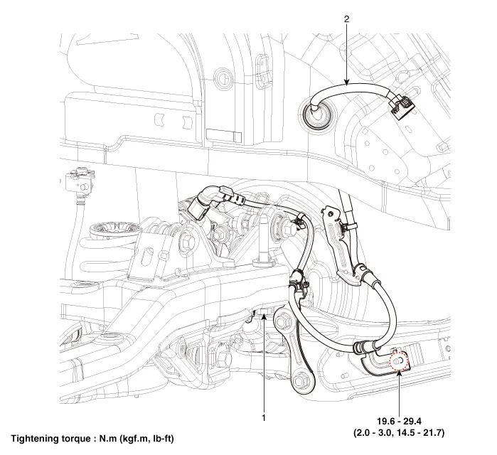
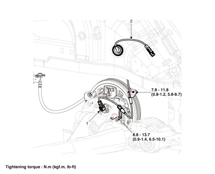
| Components |
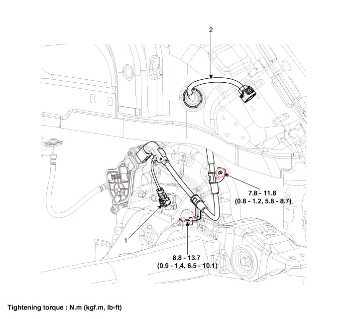
| 1. Rear wheel speed sensor | 2. Rear wheel speed sensor connector |
| 1. Rear wheel speed sensor | 2. Rear wheel speed sensor connector |
| 1. Rear wheel speed sensor | 2. Rear wheel speed sensor connector |
Repair procedures
| Removal |
| 1. | Loosen the wheel nuts slightly. Raise the vehicle, and make sure it is securely supported. |
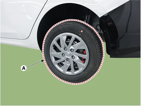
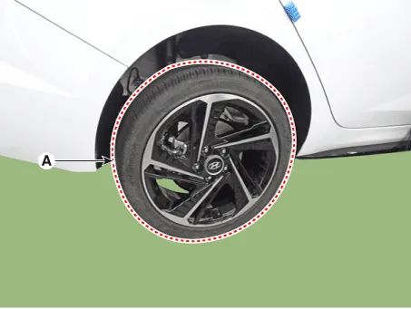
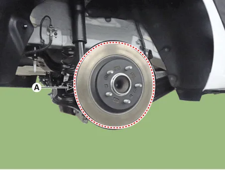
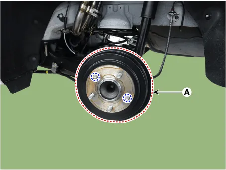
| 2. | Remove the rear wheel and tire (A) from the rear hub.
|

| 3. | Remove the rear brake caliper. (Refer to Brake System - "Rear Disc Brake") |
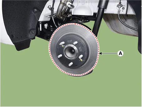
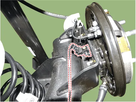
| 4. | Remove the rear brake disc (A).
|
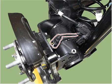
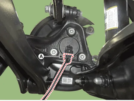
| 5. | Disconnect the rear wheel speed sensor connector (A).
|
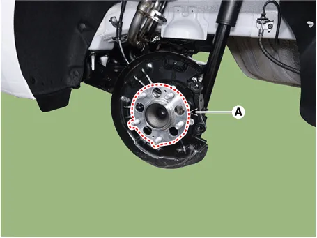
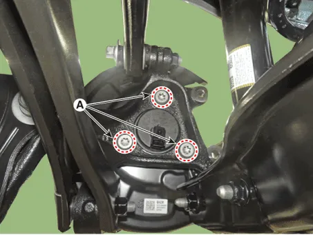
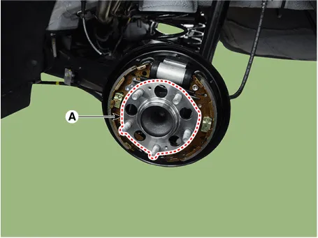
| 6. | Remove the hub bearing assembly (A) after loosening the mounting bolts.
|
| 1. | Loosen the wheel nuts slightly. Raise the vehicle, and make sure it is securely supported. |
| 2. | Remove the rear wheel and tire (A) from the rear hub.
|
| 3. | Remove the rear brake caliper. (Refer to Brake System - "Rear Disc Brake") |
| 4. | Remove the rear brake disc (A) after loosening the mounting screw.
|
| 5. | Disconnect the rear wheel speed sensor connector (A).
|
| 6. | Remove the hub bearing assembly after loosening the hub bearing mounting bolts (A).
|
| 1. | Loosen the wheel nuts slightly. Raise the vehicle, and make sure it is securely supported. |
| 2. | Remove the rear wheel and tire (A) from the rear hub.
|
| 3. | Disconnect the rear wheel speed sensor connector (A).
|
| 4. | Loosen the screw and then remove the rear drum brake (A).
|
| 5. | Loosen the hub mounting bolts and then remove the hub (A) from the torsion beam.
|
| Replacement |
| 1. | Remove the rear wheel hub bearing assembly. (Refer to Driveshaft and Axle - "Rear Hub - Carrier") |
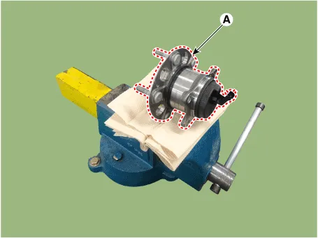
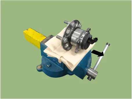
| 2. | Fix the rear hub bearing assembly (A) on the vise.
|
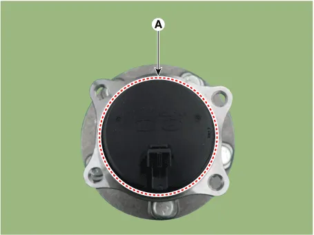
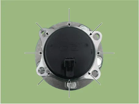
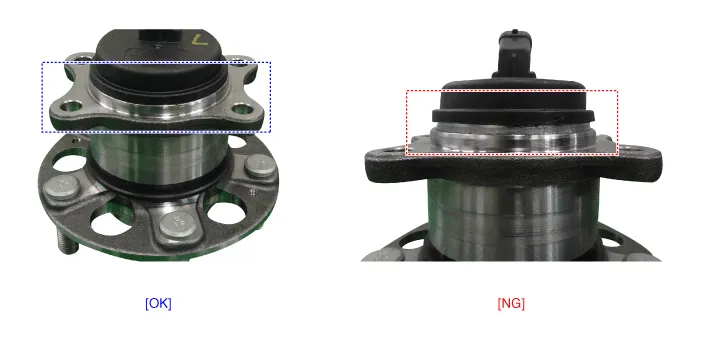
| 3. | Check the direction of the sensor cap (A).
|
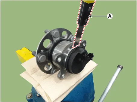
| 4. | Remove the sensor cap by hammering on a gap between sensor cap and hub bearing assembly using a scraper (A).
|
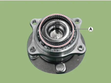
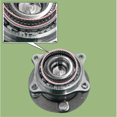
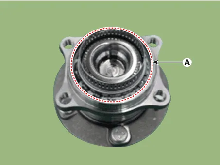
| 5. | Check if distorted or damaged the tone wheel or encoder (A).
|
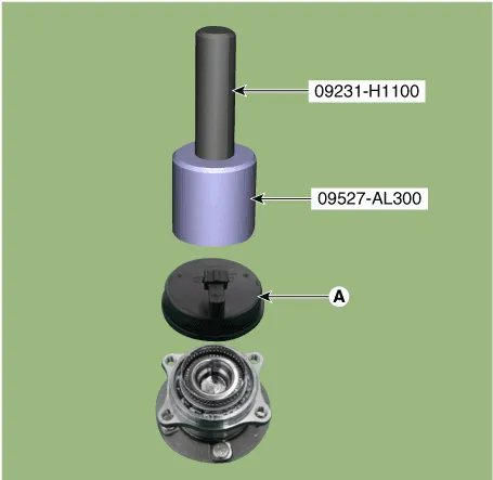
| 6. | Position the sensor cap to the same direction of sensor cap connector (A) as you checked before removing.
|
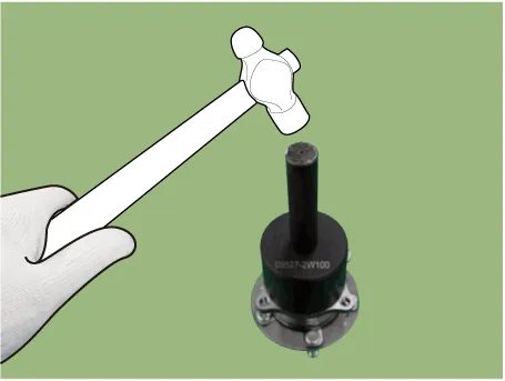
| 7. | Install the sensor cap (A) with the special service tool (09527-AL300).
|
| 8. | Install the rear wheel hub bearing assembly. (Refer to Driveshaft and Axle - "Rear Hub - Carrier") |
| Installation |
| 1. | To install, reverse the removal procedure. |
| Inspection |
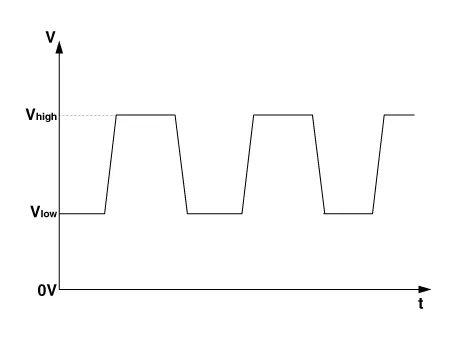
| 1. | Measure the output voltage between the terminal of the wheel speed sensor and the body ground.
|
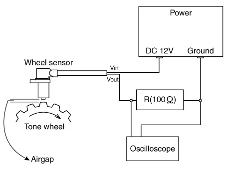
| 2. | Compare the change of the output voltage of the wheel speed sensor to the normal change of the output voltage as shown below.
|
Components and components location Components1. Front wheel speed sensor2. Front wheel speed sensor connector Repair procedures Removal1.Turn ignition switch OFF and disconnect the negative (-) battery cable.
Other information:
Hyundai Elantra (CN7) 2021-2026 Service Manual: Immobilizer Control Unit
Components and components location Components (1)With Smart KeyConnector Pin Information Pin no Connector A Connector B Connector C Connector D Connector E 1ESCL
Hyundai Elantra (CN7) 2021-2026 Service Manual: Repair procedures
Inspection1.Check for resistance between terminals in each switch position (LH).[LH : Audio + Hands free] Switch Resistance (±5%) SEEK Up430 ΩSEEK Down1.11 kΩMODE2.11 kΩMUTE3.11 kΩVolume (+)4.
Categories
- Manuals Home
- Hyundai Elantra Owners Manual
- Hyundai Elantra Service Manual
- Body Electrical System
- Brake System
- Driver assistance system
- New on site
- Most important about car
