Hyundai Elantra (CN7): Windshield Wiper/Washer / Windshield Wiper-Washer Switch
Repair procedures
| Removal |
| 1. | Disconnect the negative (-) battery terminal. |
| 2. | If it is necessary to remove multifunction switch assembly, remove the steering wheel. (Steering System - "Steering Wheel") |
| 3. | Remove the steering column upper shrouds. (Refer to Body - "Steering Column Shroud Panel") |
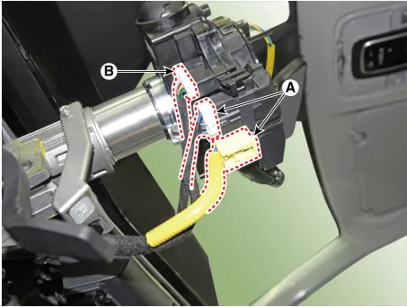
| 4. | Disconnect the clock spring connector (A) and multifunction switch connector (B).
|
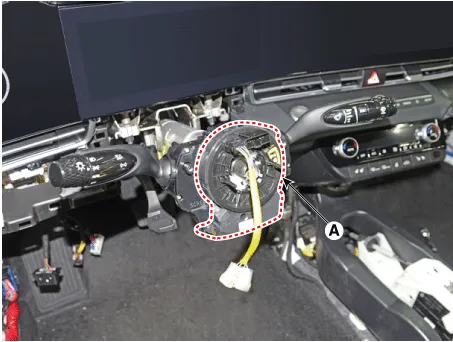
| 5. | Remove the clock spring (A).
|
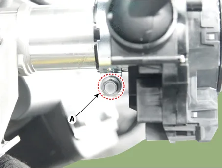
| 6. | Loosen the clamp (A) and remove the multifunction switch assembly (A).
|
| Installation |
| 1. | Install the multifunction switch. |
| 2. | Install the clock spring and steering wheel. |
| 3. | Install the steering column upper and lower shrouds. |
| 4. | Install the steering wheel. |
| Inspection |
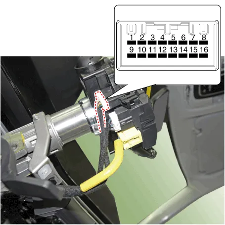
| 1. | Check for continuity between the terminals in each switch position as shown below.
|
| 1. | In the body electrical system, failure can be quickly diagnosed by using the vehicle diagnostic system (Diagnostic tool). The diagnostic system (Diagnostic tool) provides the following information.
|
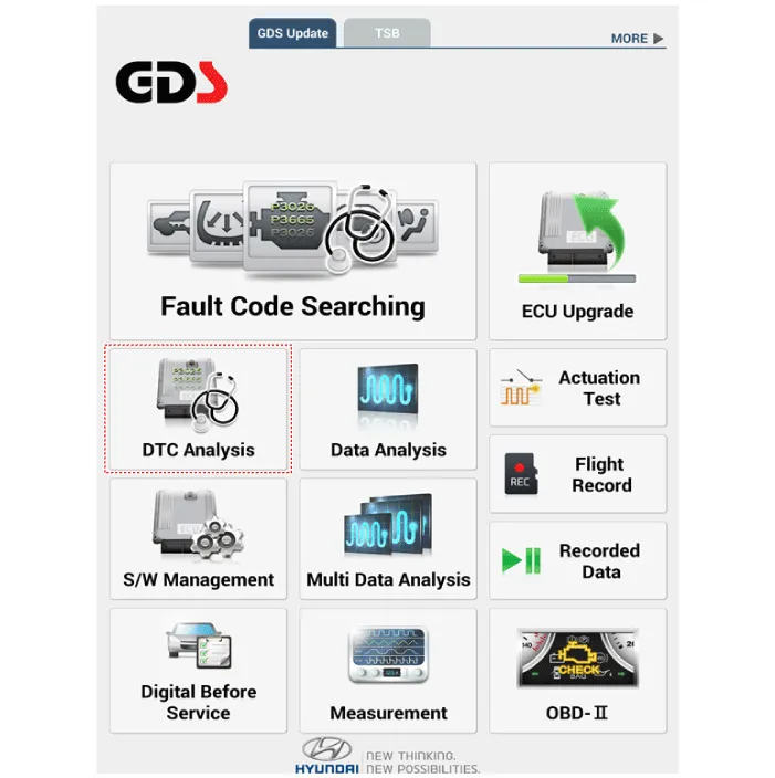
| 2. | If diagnose the vehicle by Diagnostic tool, select "DTC Analysis" and "Vehicle".
|
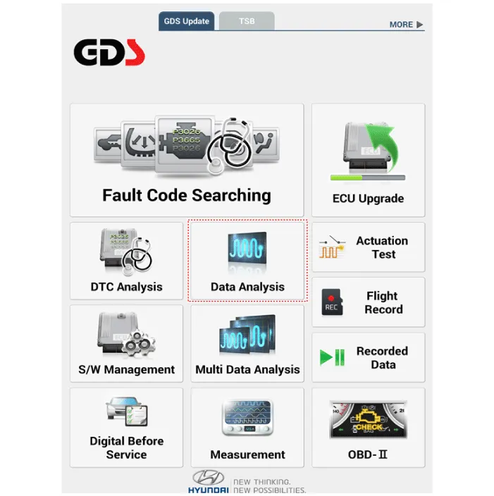
| 3. | If check current status, select the "Data Analysis" and "Car model".
|
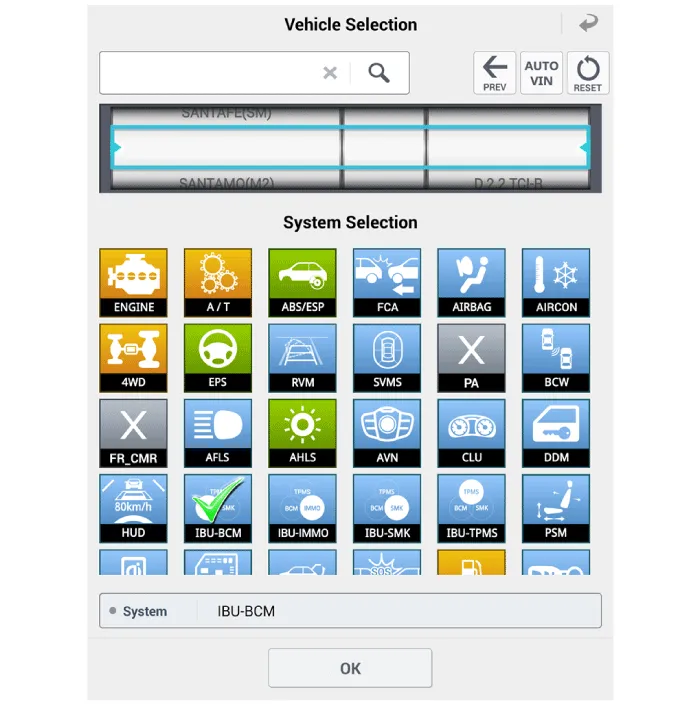
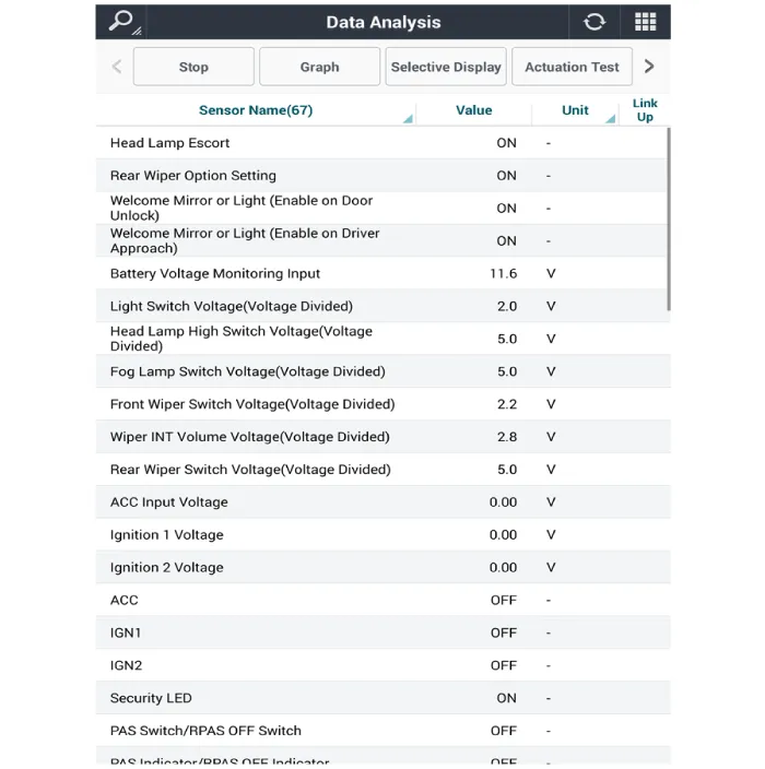
| 4. | Select the 'IBU_BCM' to search the current state of the input/output data.
|
Component Location1. Windshield wiper arm & blade2. Wiper & washer switch3. Windshield washer hose & nolzzle4. Washer motor & linkage assembly5.
Components and components location Component Location1. Cap2. Nut3. Wiper arm & blade4. Cowl top cover5. Bolt6. Wiper motor & linkage assembly7.
Other information:
Hyundai Elantra (CN7) 2021-2026 Service Manual: Evaporator Temperature Sensor
Description and operation DescriptionThe evaporator temperature sensor will detect the evaporator core temperature and interrupt compressor relay power in order to prevent evaporator from freezing by excessive cooling. The evaporator temperature sensor has the Negative Temperature Coefficient (NTC).
Hyundai Elantra (CN7) 2021-2026 Service Manual: Rear Corner Radar Unit
Specifications Specifications Items Blind-Spot Collision Warning (BCW) Blind-Spot Collision- Avoidance Assist-Rear (BCA-R) Rated voltageDC 12VOperating voltage9V - 16VOperating speed30 km/h - 255 km/h60 km/h - 180 km/hSensible distance70m Curvature radiusStart : More
Categories
- Manuals Home
- Hyundai Elantra Owners Manual
- Hyundai Elantra Service Manual
- Front Bumper
- Auto Hold. Warning messages
- Engine Mechanical System
- New on site
- Most important about car
