Hyundai Elantra (CN7): Cooling System / Coolant
Repair procedures
| Replacement and Air Bleeding |
|

|

If Diagnostic Tool is available, change the coolant and drain air according to the descriptions below.
| 1. | Make sure the engine and radiator are cool to the touch. |
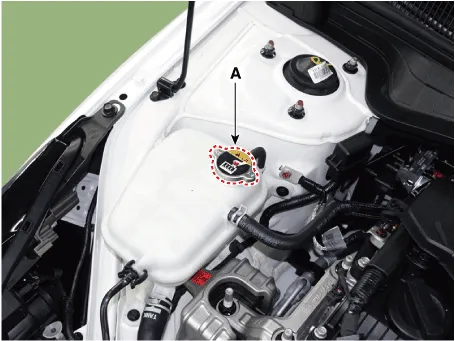
| 2. | Remove the coolant reservoir tank cap (A).
|
| 3. | Remove the engine room under cover. (Refer to Engine and Transaxle Assembly - "Engine Room Under Cover") |
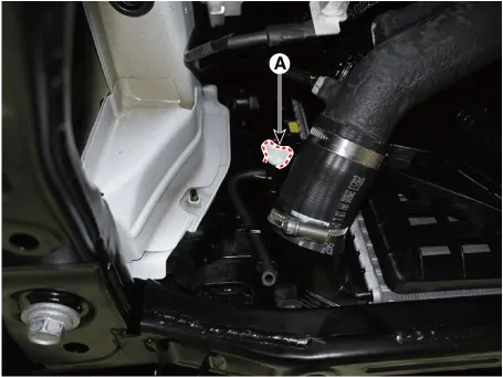
| 4. | Loosen the drain plug (A), and drain the coolant.
|
| 5. | Tighten the radiator drain plug securely after draining the coolant. |
| 6. | Clean the coolant reservoir tank after drain the coolant. |
| 7. | IG Key OFF, Fill with fluid mixture of coolant and water (45 - 60%) slowly through the coolant reservoir tank cap.
|
| 8. | Connect the diagnostic tool and then Key 'IG ON'. |
| 9. | Use the diagnostic tool to activate the "integrated thermal management module (ITM) coolant refilling mode".
|
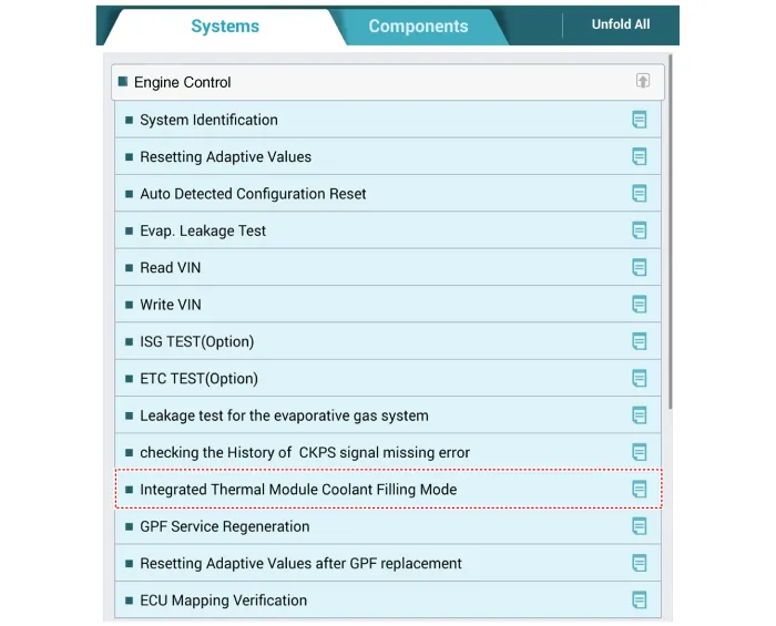
| 10. | Complete the ITM coolant refilling mode according to the procedure of the diagnostic tool. |
| 11. | Key-off and then disconnect the diagnostic tool.
|

| 12. | Install the coolant reservoir tank cap (A).
|
| 13. | Check the coolant quantity after driving the vehicle. |
| 14. | If the coolant is insufficient, replenish it. |
| 15. | Install the engineroom under cover. (Refer to Engine and Transaxle Assembly - "Engine Room Under Cover") |
If Diagnostic Tool is not available, replace the coolant and drain air according to the descriptions below.
| 1. | Make sure the engine and radiator are cool to the touch. |
| 2. | Remove the coolant reservoir tank cap (A).
|
| 3. | Remove the engine room under cover. (Refer to Engine and Transaxle Assembly - "Engine Room Under Cover") |
| 4. | Loosen the drain plug (A), and drain the coolant.
|
| 5. | Tighten the radiator drain plug securely after draining the coolant. |
| 6. | Clean the coolant reservoir tank after drain the coolant. |
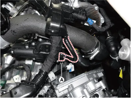
| 7. | Key-off and then disconnect the integrated thermal management module (ITM) connector (A).
|
| 8. | Fill with fluid mixture of coolant and water (45 - 60%) slowly through the coolant reservoir tank cap.
|
| 9. | After starting the engine, refill the coolant for 20 minutes used by coolant reservoir tank. |
| 10. | After shut engine off and connect the integrated thermal management module (ITM) connector (A).
|
| 11. | After starting the engine for 5 seconds, turn off the engine.
|
| 12. | Install the coolant reservoir tank cap (A).
|
| 13. | Check the coolant quantity after driving the vehicle. |
| 14. | If the coolant is insufficient, replenish it. |
| 15. | Install the engineroom under cover. (Refer to Engine and Transaxle Assembly - "Engine Room Under Cover") |
Engine Overheat Troubleshooting Inspection Remedy Visual inspectionInspect for shortage of coolant in reservoir tank .
Repair procedures Removal and Installation1.Drain the coolant.(Refer to Cooling System - "Coolant")2.Disconnect the degassing hose (A) and coolant reservoir tank hose (B).
Other information:
Hyundai Elantra (CN7) 2021-2025 Service Manual: Auto Defoging Actuator
Description and operation DescriptionThe auto defogging sensor is installed on front window glass. The sensor judges and sends signal if moisture occurs to blow out wind for defogging. The air conditioner control module receives a signal from the sensor and restrains moisture and eliminates defog by the intake actuator, A/C, auto defogging actua
Hyundai Elantra (CN7) 2021-2025 Service Manual: Description and operation
D
Categories
- Manuals Home
- Hyundai Elantra Owners Manual
- Hyundai Elantra Service Manual
- Components and components location
- Driver assistance system
- Suspension System
- New on site
- Most important about car

Copyright © 2025 www.helantra7.com - 0.0127