Hyundai Elantra (CN7): Crash Pad / Crash Pad Air Vent
Components and components location
| Component Location |
| [This illustration shows the LHD type. RHD type is symmetrical.] |
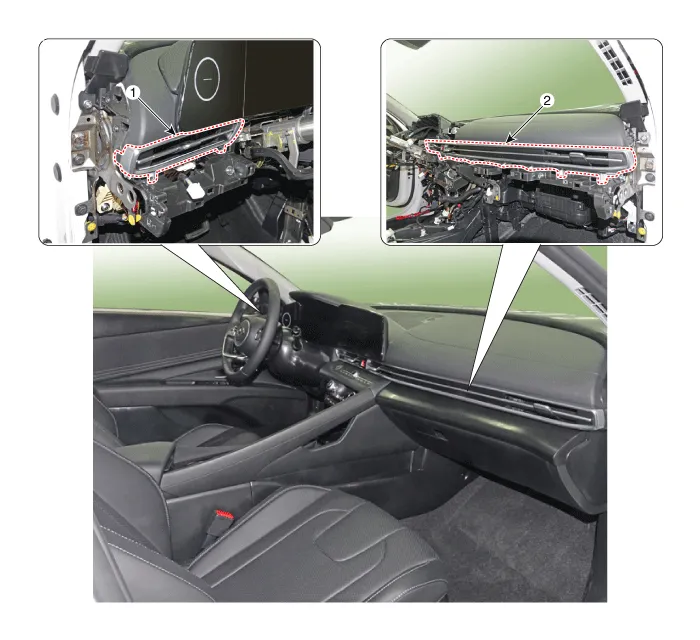
| 1. Crash pad air vent [LH] | 2. Crash pad air vent [RH] |
Repair procedures
| Replacement |
|

|

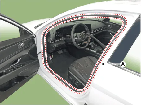
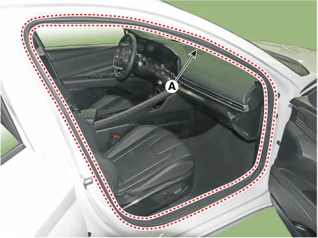
| 1. | Detach the clips, then remove the front door body side weatherstrip (A).
|
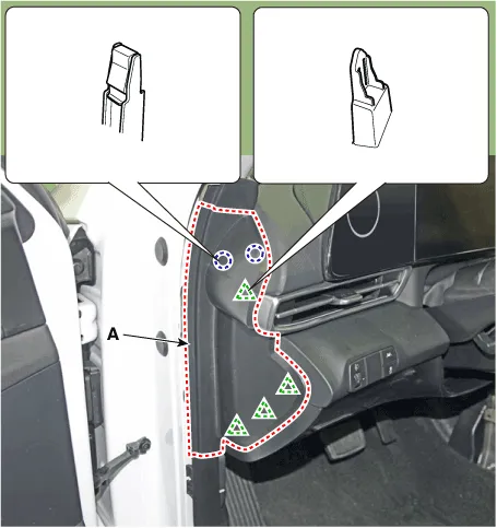
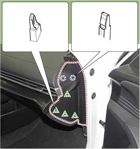
| 2. | Using a screwdriver or remover, remove the crash pad side cover (A).
|
| 3. | Remove the crash pad garnish [LH]. (Refer to Crash Pad - "Crash Pad Garnish") |
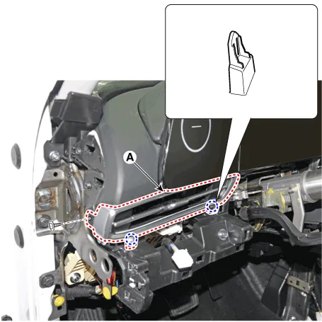
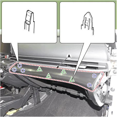
| 4. | Loosen the mounting screw, remove the crash pad air vent (A).
|
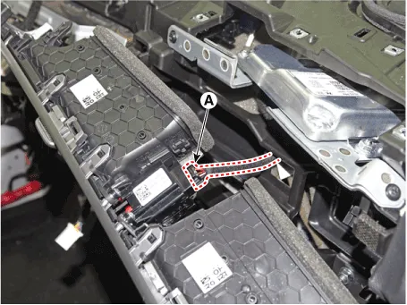
| 5. | Press the lock pin, separate the mood lamp connector (A).
|

| 6. | To install, reverse the removal procedure.
|

|
|
| 1. | Remove the instrument cluster. (Refer to Body Electrical System - "Instrument Cluster") |
| 2. | Remove the crash pad lower panel. (Refer to Crash Pad - "Crash Pad Lower Panel") |
| 3. | Detach the clips, then remove the front door body side weatherstrip (A).
|
| 4. | Using a screwdriver or remover, remove the crash pad side cover (A).
|
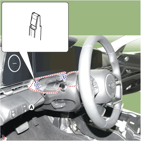
| 5. | Using a screwdriver or remover, remove the steering column shroud upper panel (A).
|
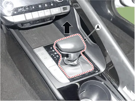
| 6. | To remove the gear knob & gear boots (A) pull both of it up.
|
| 7. | Using a screwdriver or remover, remove the floor console side garnish (A).
|
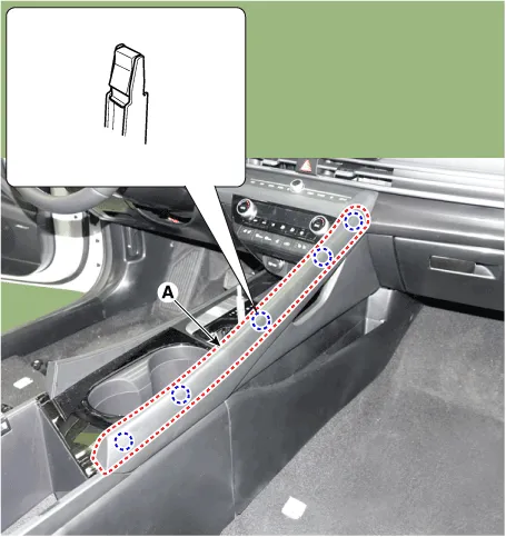
| 8. | After loosening the mounting screw and then using a screwdriver or remover, remove the console upper cover (A).
|

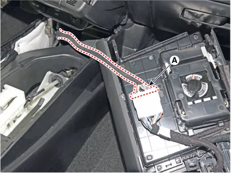
| 9. | Press the lock pin separate the console upper cover connector (A).
|
| 10. | Using a screwdriver or remover, remove the crash pad garnish [CTR] (A).
|
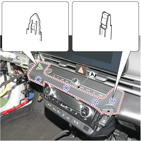
| 11. | Loosen the mounting screws, remove the A/C & heater controller unit (A).
|
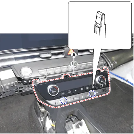
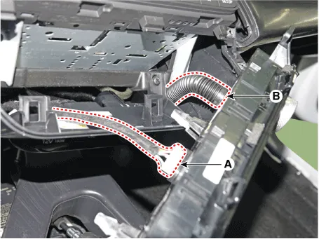
| 12. | Disconnect the A/C & heater controller connectors (A) and hose (B).
|
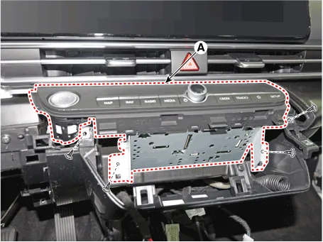
| 13. | Loosen the mounting screws, remove the AVN keyboard assembly (A).
|
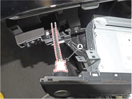
| 14. | Press the lock pin, separate the start button connector (A).
|
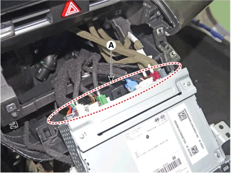
| 15. | Press the lock pin, separate the connectors (A).
|
| 16. | Loosening the mounting screws, using a screwdriver or remover, remove the crash pad garnish (A).
|
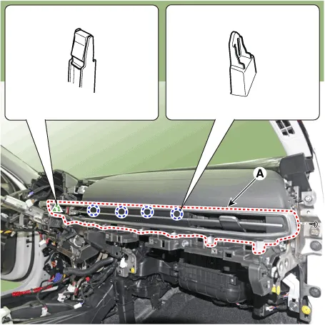
| 17. | Loosen the mounting screw, remove the crash pad air vent (A).
|
| 18. | Press the lock pin, separate the hazard switch connector (A).
|
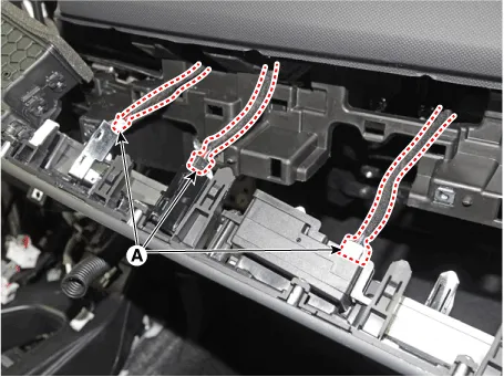
| 19. | Press the lock pin, separate the connectors (A).
|
| 20. | To install, reverse the removal procedure.
|
Components and components location Component Location [This illustration shows the LHD type. RHD type is symmetrical.]1. Steering column shroud upper panel2.
Components and components location Component Location [This illustration shows the LHD type. RHD type is symmetrical.][LH]1. Crash pad side cover [LH][RH]1.
Other information:
Hyundai Elantra (CN7) 2021-2026 Service Manual: Mode Control Actuator
Description and operation DescriptionThe mode control actuator is located at the heater unit.It adjusts the position of the mode door by operating the mode control actuator based on the signal of the A/C control unit. Pressing the mode select switch makes the mode control actuator shift in order of Vent → Bi-Level → Floor → Mix.
Hyundai Elantra (CN7) 2021-2026 Service Manual: Heater & A/C Control Unit (Manual)
Components and components location Components[This illustration shows the LHD type. RHD type is symmetrical.][Connector A] Pin No Function Pin No Function 1Low (Register specifications)4Middle Low (Register specifications)2Common (Register
Categories
- Manuals Home
- Hyundai Elantra Owners Manual
- Hyundai Elantra Service Manual
- Front Radar Unit
- Specifications
- Engine Control / Fuel System
- New on site
- Most important about car
