Hyundai Elantra (CN7): Crash Pad / Steering Column Shroud Panel
Components and components location
| [This illustration shows the LHD type. RHD type is symmetrical.] |
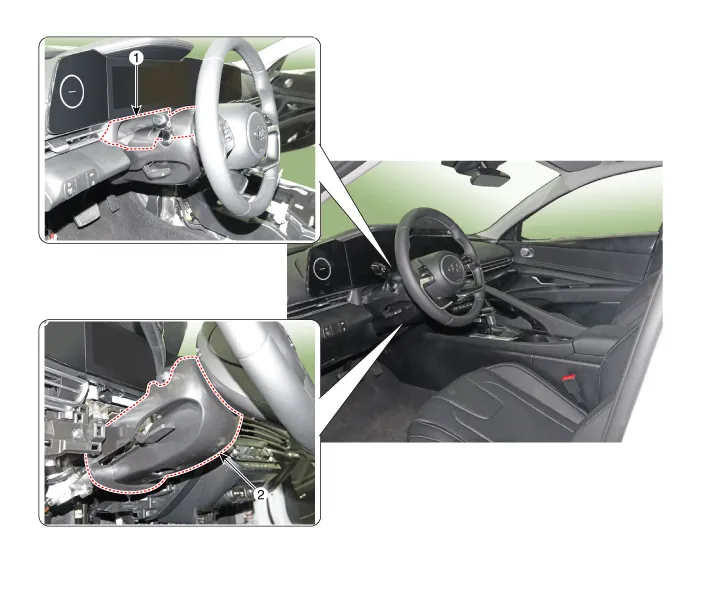
1. Steering column shroud upper panel
| 2. Steering column shroud lower panel
|
Repair procedures
[Steering column shroud upper panel]
| •
| When removing with a flat - tip screwdriver or remover, wrap protective tape around the tools to prevent damage to components. |
| •
| Put on gloves to prevent hand injuries. |
|
| •
| Take care not to bend or scratch the trim and panels. |
|
| 1. | Using a screwdriver or remover, remove the steering column shroud upper panel (A). 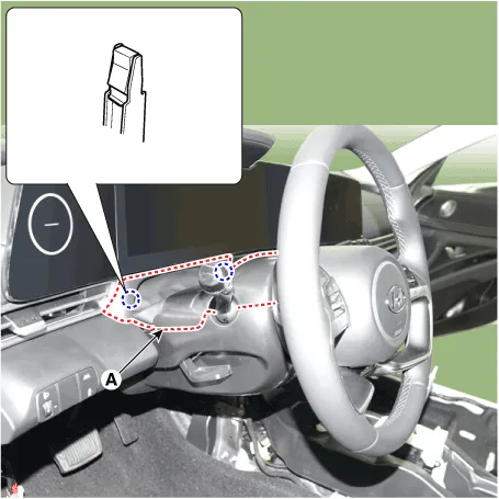
| •
| When removing the shroud upper panel, excessive force may be cause the leather to tear. 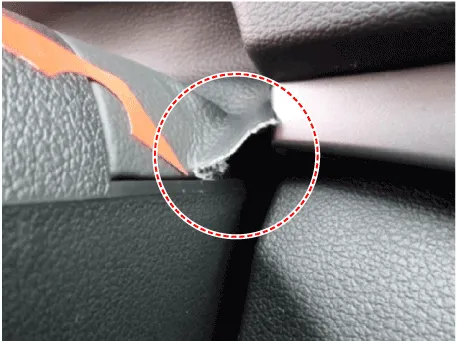
|
|
|
| 2. | To install, reverse the removal procedure. | •
| Replace any damaged clips (or pin - type retainers). |
|
|
[Steering column shroud lower panel]
| •
| When removing with a flat - tip screwdriver or remover, wrap protective tape around the tools to prevent damage to components. |
| •
| Put on gloves to prevent hand injuries. |
|
| •
| Take care not to bend or scratch the trim and panels. |
|
| 1. | Remove the crash pad lower panel. (Refer to Crash Pad - "Crash Pad Lower Panel") |
| 2. | Loosen the mounting screws by turning the steering wheel to the left and right, and remove the steering column shroud lower panel (A). 
|
| 3. | To install, reverse the removal procedure. | •
| Replace any damaged clips (or pin - type retainers). |
|
|
Components and components location
Component Location [This illustration shows the LHD type. RHD type is symmetrical.]1. Glove box housing cover
Repair procedures
Replacement
•
When removing with a flat - tip screwdriver or remover, wrap protective tape around the tools to prevent damage to components.
Components and components location
Component Location [This illustration shows the LHD type. RHD type is symmetrical.]1. Crash pad air vent [LH]2. Crash pad air vent [RH]
Repair procedures
Replacement[LH]
•
When removing with a flat - tip screwdriver or remover, wrap protective tape around the tools to prevent damage to components.
Other information:
Components and positions
Components
Circuit diagram
Circuit Diagram
Repair procedures
Removal
•
Handling wireless charging system parts by wet hands may cause electric shock. 1.Disconnect the negative (-) battery terminal.
C


