Hyundai Elantra (CN7): Crash Pad / Glove Box Housing Cover
Components and components location
| Component Location |
| [This illustration shows the LHD type. RHD type is symmetrical.] |
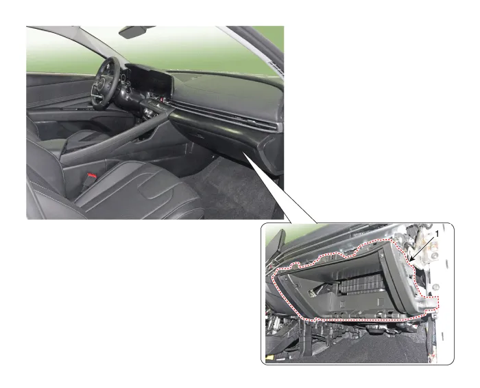
| 1. Glove box housing cover |
Repair procedures
| Replacement |
|

|

| 1. | Remove the golve box. (Refer to Crash Pad - "Glove Box") |
| 2. | Remove the crash pad side cover [RH]. (Refer to Crash Pad - "Crash Pad Side Cover") |
| 3. | (Remove the crash pad garnish [RH]. (Refer to Crash Pad - "Crash Pad Garnish") |
| 4. | Loosen the mounting screws and bolts, remove the glove box housing cover (A).
|
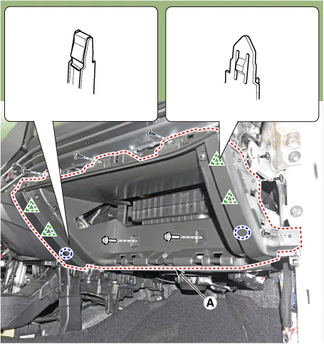
| 5. | To install, reverse the removal procedure.
|

Components and components location Components Location[This illustration shows the LHD type. RHD type is symmetrical.]1. Glove box Repair procedures Replacement • When removing with a flat - tip screwdriver or remover, wrap protective tape around the tools to prevent damage to components.
Components and components location Component Location [This illustration shows the LHD type. RHD type is symmetrical.]1. Steering column shroud upper panel2.
Other information:
Hyundai Elantra (CN7) 2021-2026 Service Manual: Rear Combination Lamp
Repair procedures RemovalOutside Combination Lamp1.Disconnect the negative (-) battery terminal.2.Remove the combination lamp cover (A).3.Disconnect the rear combination lamp connector (A).4.Loosen the mounting nuts and remove the rear conbination lamp (A).
Hyundai Elantra (CN7) 2021-2026 Service Manual: Auto Defoging Actuator
Description and operation DescriptionThe auto defogging sensor is installed on front window glass. The sensor judges and sends signal if moisture occurs to blow out wind for defogging. The air conditioner control module receives a signal from the sensor and restrains moisture and eliminates defog by the intake actuator, A/C, auto defogging actua
Categories
- Manuals Home
- Hyundai Elantra Owners Manual
- Hyundai Elantra Service Manual
- Body Electrical System
- Engine Mechanical System
- Brake System
- New on site
- Most important about car
