Hyundai Elantra (CN7): Crash Pad / Steering Column Shroud Panel
Components and components location
| [This illustration shows the LHD type. RHD type is symmetrical.] |
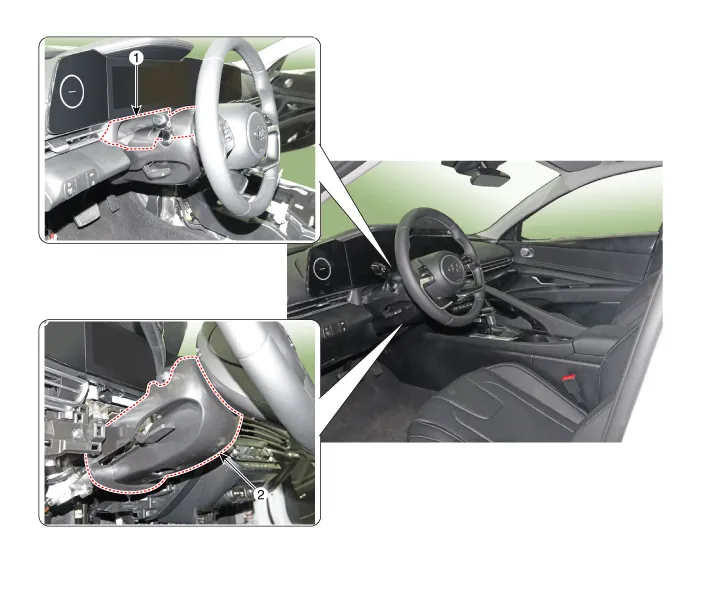
1. Steering column shroud upper panel
| 2. Steering column shroud lower panel
|
Repair procedures
[Steering column shroud upper panel]
| •
| When removing with a flat - tip screwdriver or remover, wrap protective tape around the tools to prevent damage to components. |
| •
| Put on gloves to prevent hand injuries. |
|
| •
| Take care not to bend or scratch the trim and panels. |
|
| 1. | Using a screwdriver or remover, remove the steering column shroud upper panel (A). 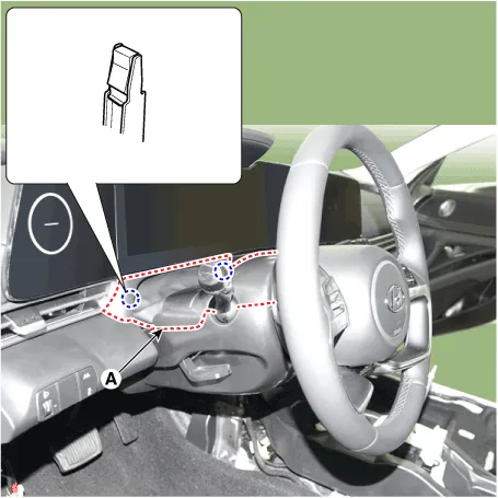
| •
| When removing the shroud upper panel, excessive force may be cause the leather to tear. 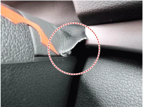
|
|
|
| 2. | To install, reverse the removal procedure. | •
| Replace any damaged clips (or pin - type retainers). |
|
|
[Steering column shroud lower panel]
| •
| When removing with a flat - tip screwdriver or remover, wrap protective tape around the tools to prevent damage to components. |
| •
| Put on gloves to prevent hand injuries. |
|
| •
| Take care not to bend or scratch the trim and panels. |
|
| 1. | Remove the crash pad lower panel. (Refer to Crash Pad - "Crash Pad Lower Panel") |
| 2. | Loosen the mounting screws by turning the steering wheel to the left and right, and remove the steering column shroud lower panel (A). 
|
| 3. | To install, reverse the removal procedure. | •
| Replace any damaged clips (or pin - type retainers). |
|
|
Components and components location
Component Location [This illustration shows the LHD type. RHD type is symmetrical.]1. Glove box housing cover
Repair procedures
Replacement
•
When removing with a flat - tip screwdriver or remover, wrap protective tape around the tools to prevent damage to components.
Components and components location
Component Location [This illustration shows the LHD type. RHD type is symmetrical.]1. Crash pad air vent [LH]2. Crash pad air vent [RH]
Repair procedures
Replacement[LH]
•
When removing with a flat - tip screwdriver or remover, wrap protective tape around the tools to prevent damage to components.
Other information:
Description and operation
DescriptionThe temperature control actuator is located at the heater unit. It regulates the temperature by the procedure as follows. The signal from the control unit adjusts the position of the temperature door by operating the temperature switch.
Components and components location
Components[This illustration shows the LHD type. RHD type is symmetrical.][Connector A]
Pin No
Function
Pin No
Function
1Battery9IGN22ILL+ (TAIL)10ISG Battery (+)3-11IGN14LIN BUS12HTD5-13-6-14-7-15-8RHEO (



