Hyundai Elantra (CN7): Crash Pad / Crash Pad Air Vent
Components and components location
| Component Location |
| [This illustration shows the LHD type. RHD type is symmetrical.] |
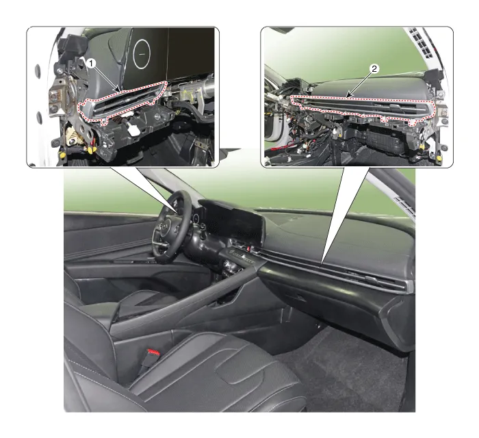
| 1. Crash pad air vent [LH] | 2. Crash pad air vent [RH] |
Repair procedures
| Replacement |
|

|

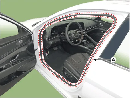
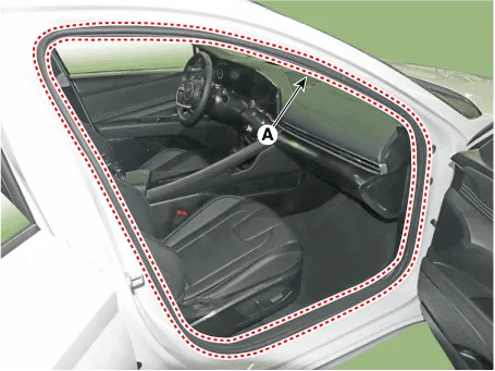
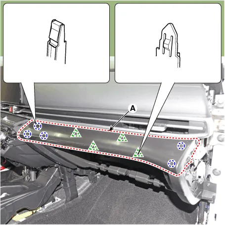
| 1. | Detach the clips, then remove the front door body side weatherstrip (A).
|
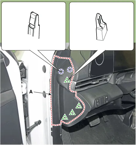
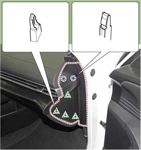
| 2. | Using a screwdriver or remover, remove the crash pad side cover (A).
|
| 3. | Remove the crash pad garnish [LH]. (Refer to Crash Pad - "Crash Pad Garnish") |
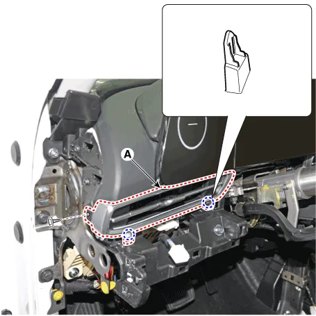
| 4. | Loosen the mounting screw, remove the crash pad air vent (A).
|
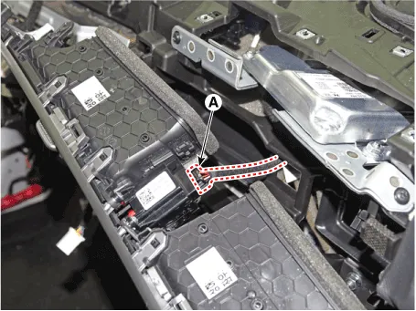
| 5. | Press the lock pin, separate the mood lamp connector (A).
|

| 6. | To install, reverse the removal procedure.
|

|
|
| 1. | Remove the instrument cluster. (Refer to Body Electrical System - "Instrument Cluster") |
| 2. | Remove the crash pad lower panel. (Refer to Crash Pad - "Crash Pad Lower Panel") |
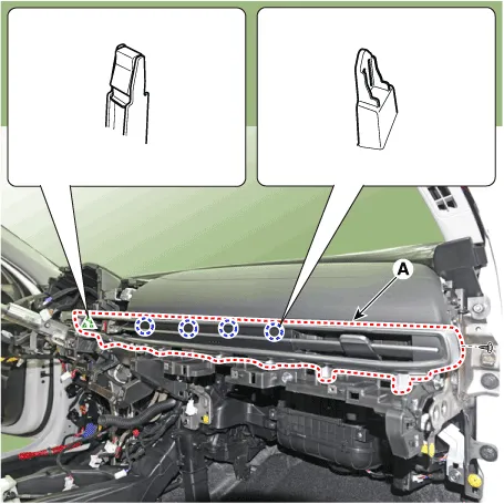
| 3. | Detach the clips, then remove the front door body side weatherstrip (A).
|
| 4. | Using a screwdriver or remover, remove the crash pad side cover (A).
|
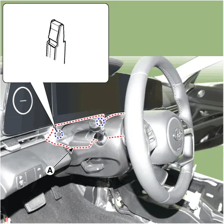
| 5. | Using a screwdriver or remover, remove the steering column shroud upper panel (A).
|
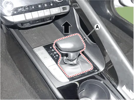
| 6. | To remove the gear knob & gear boots (A) pull both of it up.
|
| 7. | Using a screwdriver or remover, remove the floor console side garnish (A).
|
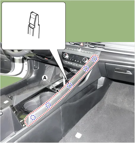
| 8. | After loosening the mounting screw and then using a screwdriver or remover, remove the console upper cover (A).
|

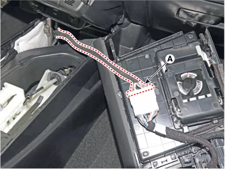
| 9. | Press the lock pin separate the console upper cover connector (A).
|
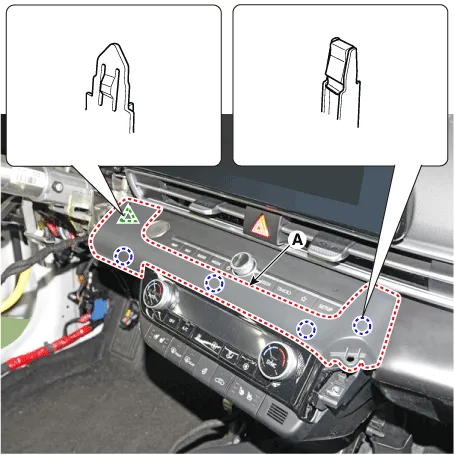
| 10. | Using a screwdriver or remover, remove the crash pad garnish [CTR] (A).
|
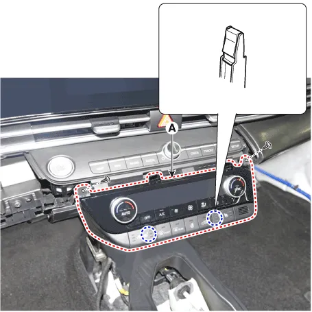
| 11. | Loosen the mounting screws, remove the A/C & heater controller unit (A).
|
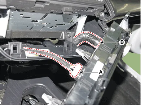
| 12. | Disconnect the A/C & heater controller connectors (A) and hose (B).
|
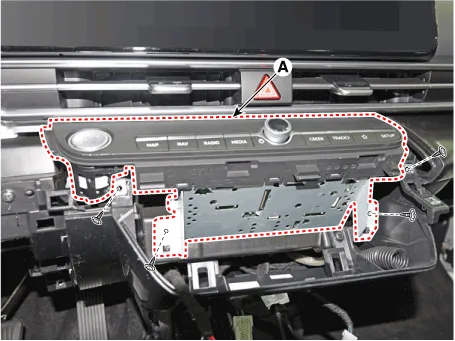
| 13. | Loosen the mounting screws, remove the AVN keyboard assembly (A).
|
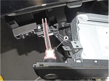
| 14. | Press the lock pin, separate the start button connector (A).
|
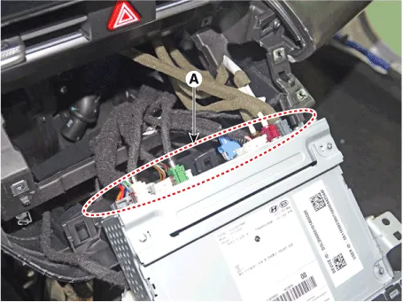
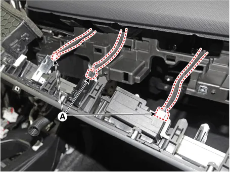
| 15. | Press the lock pin, separate the connectors (A).
|
| 16. | Loosening the mounting screws, using a screwdriver or remover, remove the crash pad garnish (A).
|
| 17. | Loosen the mounting screw, remove the crash pad air vent (A).
|
| 18. | Press the lock pin, separate the hazard switch connector (A).
|
| 19. | Press the lock pin, separate the connectors (A).
|
| 20. | To install, reverse the removal procedure.
|
Components and components location Component Location [This illustration shows the LHD type. RHD type is symmetrical.]1. Steering column shroud upper panel2.
Components and components location Component Location [This illustration shows the LHD type. RHD type is symmetrical.][LH]1. Crash pad side cover [LH][RH]1.
Other information:
Hyundai Elantra (CN7) 2021-2026 Service Manual: Compressor
Description and operation DescriptionThe compressor is the power unit of the A/C system.It is located on the side of engine block and driven by a V-belt of the engine.The compressor changes low pressure and low temperature refrigerant gas into high pressure and high temperature refrigerant gas.
Hyundai Elantra (CN7) 2021-2026 Service Manual: Smart Cruise Control (SCC) Switch
Schematic diagrams Circuit DiagramTRIP / SCC / LFA Repair procedures Inspection1.Check for resistance between terminals in each switch position (LH).[LH : Audio + Hands free] Switch Resistance (±5%) SEEK Up430 ΩSEEK Down1.
Categories
- Manuals Home
- Hyundai Elantra Owners Manual
- Hyundai Elantra Service Manual
- Integrated Thermal Management Module (ITM)
- Rear Seats
- Brake System
- New on site
- Most important about car
