Hyundai Elantra (CN7): Dual Clutch Transmission Control System / Inhibitor Switch
Description and operation
| Description |
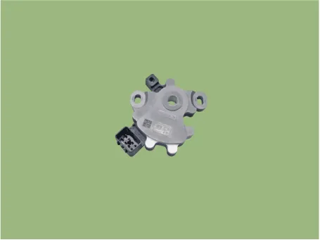
| • | The inhibitor switch is installed on top of transmission, and is connected to the shift lever through shift cable. |
| • | Inhibitor switch signals (S1, S2, S3, S4) are transmitted to the TCM according to the driver's shift lever control.
|
Specifications
| Specifications |
|
Item
|
Specification
|
| Power supply | 12V |
| Output type | Combination of output signals |
| Signal Code Table |
|
|
P
|
Pst (P - R)
|
R
|
Nst (R - N)
|
N
|
N-D
|
D
|
| Signal "1" | 12V | 12V | 0 | 0 | 0 | 0 | 0 |
| Signal "2" | 0 | 12V | 12V | 12V | 0 | 0 | 0 |
| Signal "3" | 0 | 0 | 0 | 12V | 12V | 12V | 0 |
| Signal "4" | 0 | 0 | 0 | 0 | 0 | 12V | 12V |
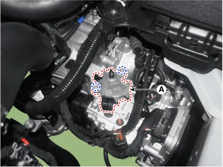
Components and components location
| Components |
| 1. Inhibitor switch | 2. Manual control lever |
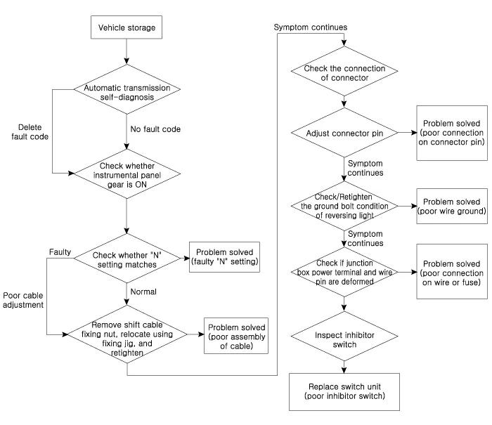
Troubleshooting
| Fault Diagnosis |
| Fault Diagnosis for Symptom |
|
Major Symptom
|
Expected Cause
|
Items to Check and Measures
|
| Shift lever not operating Gear not marked on cluster Shock occurs while shifting lever Warning lamp ON Engine OFF while vehicle is parked | Inhibitor switch circuit abnormal Inhibitor switch function abnormal | Check the inspection FLOW and replace the inhibitor switch |
| Inhibitor switch "N" setting faulty | Adjust "N" setting using "N" setting jig (refer to automatic transmission system - "inhibitor switch") | |
| Shift cable separation faulty | Adjust shift cable separation (refer to automatic transmission system - "inhibitor switch") | |
| Poor ground condition on reversing light circuit | Check the ground condition on reversing light and retighten it | |
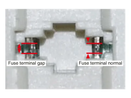
| Inhibitor switch vehicle side circuit abnormal | Check the connection of junction box power terminal, fuse (TCU2) terminal and replace the junction box or adjust the gap | |
| Check inside the inhibitor switch connector for foreign substance and whether terminal is bent | ||
| Poor ground condition on inhibitor switch wire | Check the ground condition of wire and retighten it | |
| Poor inhibitor unit (disconnection/short-circuit) | Replace inhibitor switch (refer to inhibitor switch inspection) |
Repair procedures
| Inspection |
|

| 1. | Inspect DTC code. |
| 2. | Inspect whether N setting matches.
|
| 3. | Inspect shift cable separation.
|
| 4. | Inspect whether connector is connected.
|
| 5. | Inspect ground condition on reversing light circuit.
|
| 6. | Inspect wiring connection on junction box power terminal and fuse lamp.
|
| 7. | Inspect inhibitor switch signal.
|
| Removal |
| 1. | Make sure vehicle does not roll before setting shift lever to "N" position. |
| 2. | Turn ignition switch OFF and disconnect the battery negative (-) terminal. |
| 3. | Remove the air cleaner assembly and air duct. (Refer to Engine Mechnical System - "Air cleaner") |
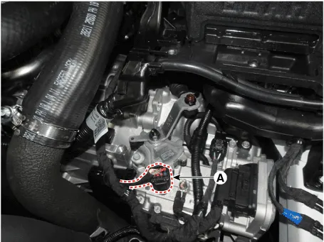
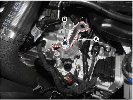
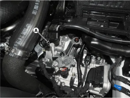
| 4. | Disconnect the inhibitor switch connector (B).
|
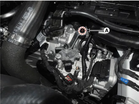
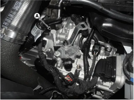
| 5. | Loosen the shift cable mounting nut (A).
|
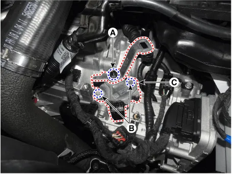
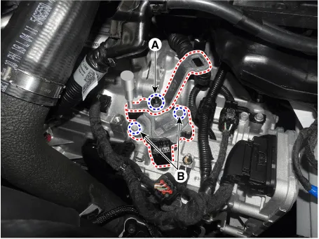
| 6. | Loosen the manual lever mounting nut (A) and inhibitor swtich mounting bolts (B) and then remove the inhibitor switch (C).
|
| Installation |
| 1. | Check that the shift lever is placed in the "N" position. |
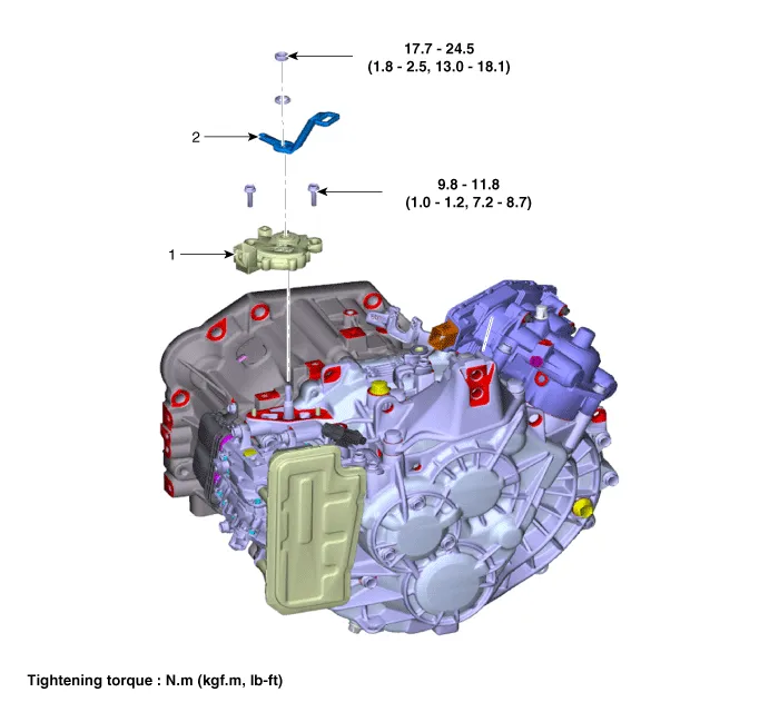
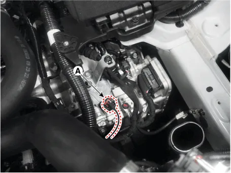
| 2. | Lightly tighten the inhibitor switch mounting bolts after installing the inhibitor switch (A).
|
| 3. | Lightly tighten the manual control lever mounting nut (B) after installing the manual control lever (A).
|
| 4. | Align the hole in the manual control lever with the "N" position hole of the inhibitor switch and then insert the inhibitor switch guide pin (SST No. : 09480 - A3800) (A) in the matched hole.
|
| 5. | Tighten the nut (A), bolts (B) with the specified torque.
|
| 6. | Lightly tighten the nut (A) after connected the shift cable in the manual control lever. |
| 7. | Push shift cable lightly to "F" direction shown to eliminate free play of shift cable. |
| 8. | Tighten the nut (A) with the specified torque.
|
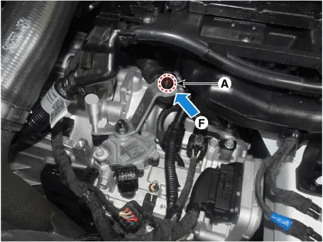
| 9. | Connect the inhibitor switch connector (A).
|
| 10. | Remove the inhibitor switch guide pin (SST No. : 09480-A3800) from the hole.
|
| 11. | Install the air cleaner and air duct. (Refer to Engine Mechanical System - "Air Cleaner")
|

Description and operation Description• Components location : DCT (Dual Clutch Transmission)• Function The input shaft speed sensor is important in that it detects the input shaft RPM and sends this information to the Transmission Control Module (TCM).
Components and components location Components1. Shift lever knob & boots assembly2. Shift lever assembly3. Shift cable4. Manual control lever5. Shift cable retainer Repair procedures Removal1.
Other information:
Hyundai Elantra (CN7) 2021-2025 Service Manual: Repair procedures
Refrigerant System Service Basics (R-134a)Refrigerant Recovery Use only service equipment that is U.L-listed and is certified to meet the requirements of SAE J2210 to remove HFC-134a(R-134a) from the air conditioning system. • Air conditioning refrigerant or lubricant vapor can irritate your eyes, nose, or
Hyundai Elantra (CN7) 2021-2025 Service Manual: Climate Control Air Filter
Description and operation Description The climate control air filter is located in the blower unit. It eliminates foreign materials and odor. The particle filter performs a role as an odor filter as well as a conventional dust filter to ensure comfortable interior environment.
Categories
- Manuals Home
- Hyundai Elantra Owners Manual
- Hyundai Elantra Service Manual
- Engine Control / Fuel System
- Body Electrical System
- Suspension System
- New on site
- Most important about car
