Hyundai Elantra (CN7): Intake And Exhaust System / Muffler
Components and components location
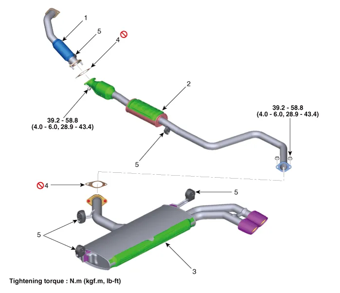
1. Front muffler
2. Catalytic converter & Center muffler
3. Rear muffler
| 4. Gasket
5. Hanger
|
Repair procedures
Front Muffler
| 1. | Disconnect the battery negative terminal. |
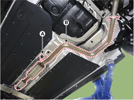
| 2. | Disconnect the oxygen sensor connector (A). 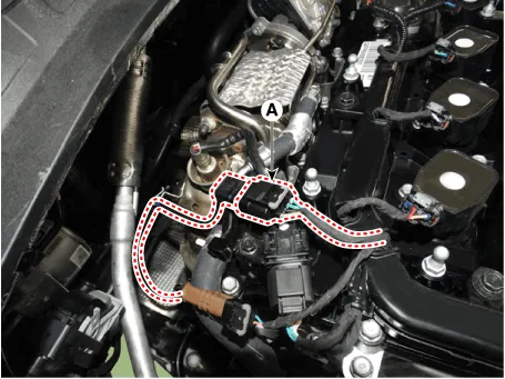
|
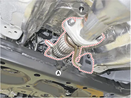
| 3. | Remove the heat protector (A). Tightening torque : 9.8 - 11.8 N.m (1.0 - 1.2 kgf.m, 7.2 - 8.7 lb-ft) |
|
| 4. | Remove the front muffler (A) after disconnecting the hanger. Tightening torque : 39.2 - 58.8 N.m (4.0 - 6.0 kgf.m, 28.9 - 43.4 lb-ft) |
|
| 5. | Install in the reverse order of removal. | •
| When installing, replace with new gaskets. |
|
|
Catalytic Converter & Center Muffler
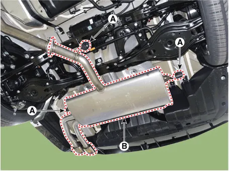
| 1. | Remove the catalytic converter & center muffler. | (1) | Disconnect the hanger (A). |
| (2) | Remove the catalytic converter & center muffler (B). Tightening torque : 39.2 - 58.8 N.m (4.0 - 6.0 kgf.m, 28.9 - 43.4 lb-ft) |
|
|
| 2. | Install in the reverse order of removal. | •
| When installing, replace with new gaskets. |
|
|
Rear Muffler
| 1. | Remove the rear muffler. | (1) | Disconnect the hanger (A). |
| (2) | Remove the rear muffler (B). Tightening torque : 39.2 - 58.8 N.m (4.0 - 6.0 kgf.m, 28.9 - 43.4 lb-ft) |
|
|
| 2. | Install in the reverse order of removal. | •
| When installing, replace with new gaskets. |
|
|
Replacement procedure of center muffler using clamp
Under warranty : Replace the center muffler assembly.
Out of warranty : It is available to replace the center muffler as the procedure below.
| 1. | Check that the clamping part of the center muffler assembly is damaged or deformed. If the muffler is too corroded to clamp, replace the center muffler assembly. 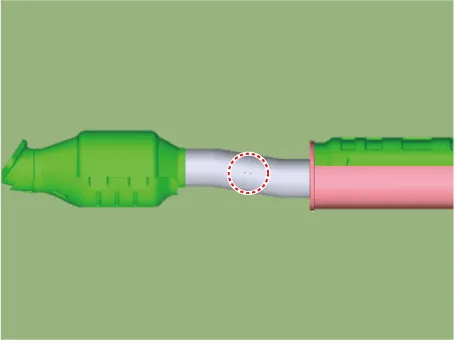
|
| 2. | Remove the catalytic converter & center muffler. | (1) | Disconnect the hanger (A). |
| (2) | Remove the catalytic converter & center muffler (B). Tightening torque : 39.2 - 58.8 N.m (4.0 - 6.0 kgf.m, 28.9 - 43.4 lb-ft) |
|
|
| 3. | Cut the center muffler as the instruction below. | –
| Cut the front dent of the muffler. 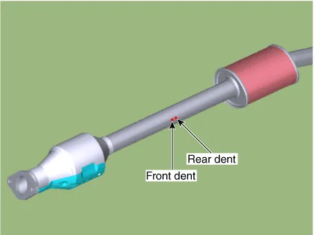
|
[A/S muffler] | –
| Cut the rear dent of the A/S muffler. 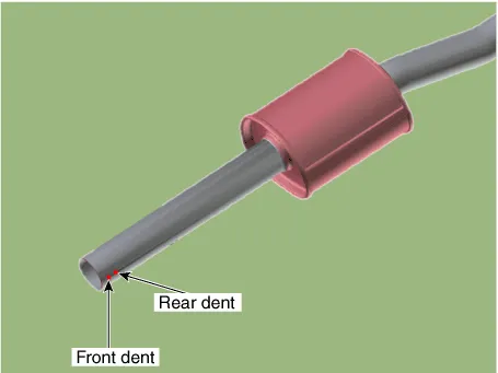
|
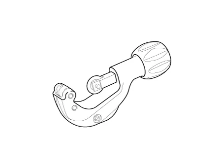
| •
| To prevent a leak, remove the rust on the clamping part or the burr on the cutting part. |
| •
| Cut the pipe vertically. |
|
| •
| Pipe cutter available to cut the pipe vertically. |
|
|
| 4. | Install the center muffler. | (1) | Install the catalytic converter (A) and the center muffler (B) for A/S by tightening the nuts lightly, not completely. 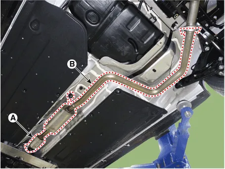
| •
| When installing the muffler, replace the gasket with new one. |
|
|
| (2) | Put the clamp (A) between the cutting part of each pipe and tighten the clamp lightly, not completely. 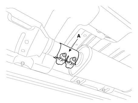
|
| (3) | Tighten the catalytic converter and the center muffler with specified torque. Tightening torque : 39.2 ~ 58.8 N.m (4.0 ~ 6.0 kgf.m, 28.9 ~ 43.4 lb-ft) |
|
| (4) | Compare the gap between the tail pipe(or tail trim) and the rear bumper with the record measured before removing the center muffler assembly. | •
| If the tail pipe is installed differently compared to the initial position, the bumper might be damaged by the pipe heat or interfere between the tail pipe and the rear bumper. |
|
|
| (5) | Do not tighten the clamp at a time. Tighten the clamp nuts to the specified torque, by turns. Tightening torque : 17.6 ~ 23.5 N.m (1.8 ~ 2.4 kgf.m, 13.0 ~ 17.4 lb-ft) |
| •
| Do not reuse the clamp that was tightened completely. It may cause leak to reuse the clamp that was tightened completely. |
|
|
|
Repair procedures
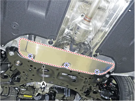
Removal and Installation1.Disconnect the battery negative terminal.2.Remove the engine room under cover.(Refer to Engine and Transaxle Assembly - "Engine Room Under Cover")3.
Other information:
C
Schematic diagrams
Circuit DiagramTRIP / SCC / LFA
Repair procedures
Inspection1.Check for resistance between terminals in each switch position (LH).[LH : Audio + Hands free] Switch Resistance (±5%) SEEK Up430 ΩSEEK Down1.

