Hyundai Elantra (CN7): Rear Bumper / Rear Bumper beam Assembly
Components and components location
| Component Location |
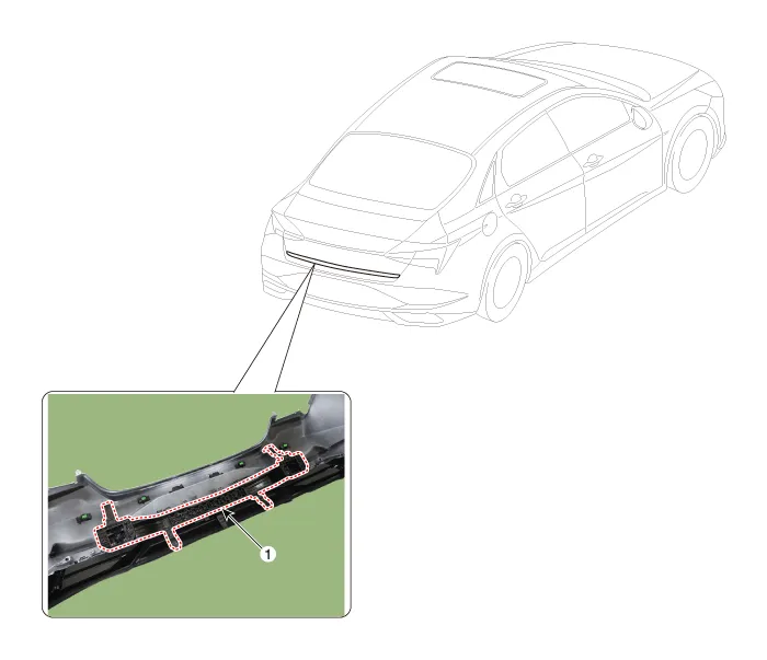
| 1. Rear bumper beam assembly |
Repair procedures
| Replacement |
|

|

| 1. | Remove the rear bumper assembly. (Refer to Rear Bumper - "Rear Bumper Assembly") |
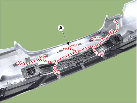
| 2. | Press the lock pin, then detach the connector, remove the wiring hanes (A).
|
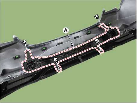
| 3. | Remove fixing clips, then remove the rear bumper beam assembly (A).
|
| 4. | Install in the reverse order of removal.
|

Components and components location Component Location1. Rear bumper assembly Repair procedures Replacement • When removing with a flat-tip screwdriver or remover, wrap protective tape around the tools to prevent damage to components.
Other information:
Hyundai Elantra (CN7) 2021-2025 Service Manual: Wireless Power Charging Unit
Components and positions Components Circuit diagram Circuit Diagram Repair procedures Removal • Handling wireless charging system parts by wet hands may cause electric shock. 1.Disconnect the negative (-) battery terminal.
Hyundai Elantra (CN7) 2021-2025 Service Manual: Heater Control Unit
Components and components location Component Location1. Heater control unitComponents[Connector A] Pin No Function Pin No Function 1Mode control actuator (Feedback)21Mode control actuator (Vent)2Intake actuator (Feedback)22Mode control actu
Categories
- Manuals Home
- Hyundai Elantra Owners Manual
- Hyundai Elantra Service Manual
- Front Bumper
- Vehicle Information
- Engine Control / Fuel System
- New on site
- Most important about car
