Hyundai Elantra (CN7): ESC (Electronic Stability Control) System / Rear Wheel Speed Sensor
Components and components location
| Components |
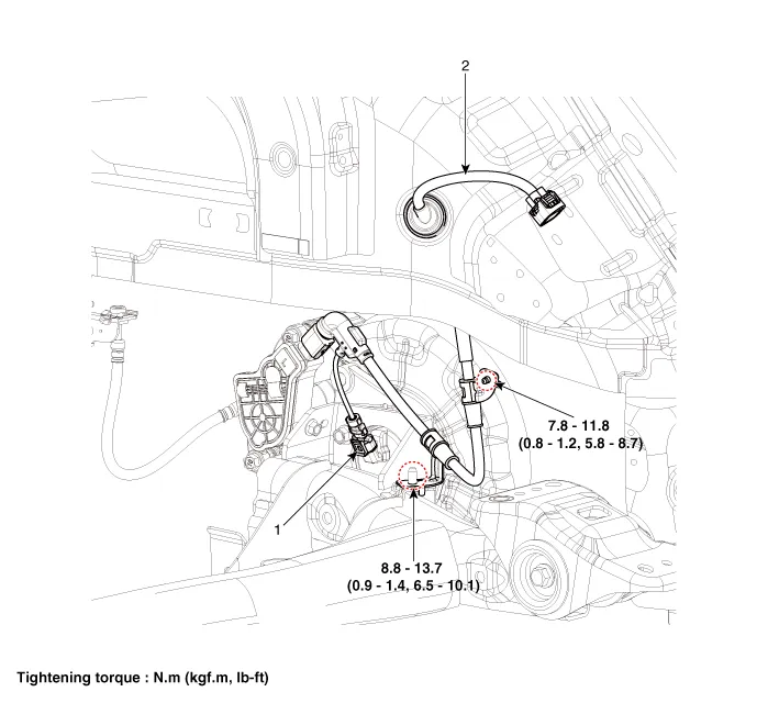
| 1. Rear wheel speed sensor | 2. Rear wheel speed sensor connector |
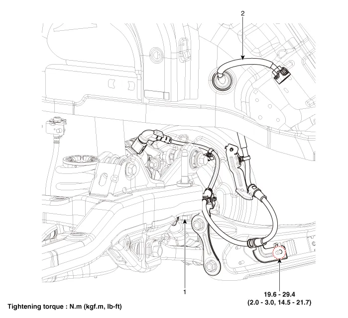
| 1. Rear wheel speed sensor | 2. Rear wheel speed sensor connector |
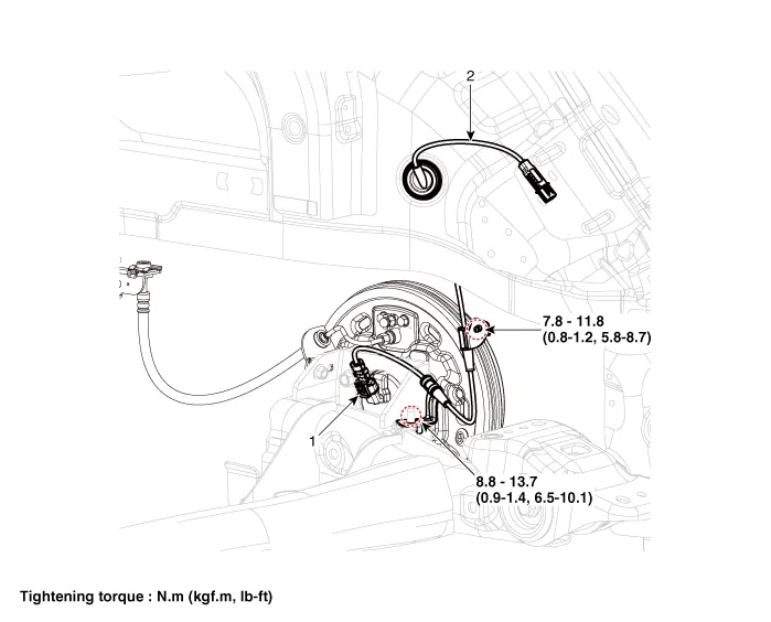
| 1. Rear wheel speed sensor | 2. Rear wheel speed sensor connector |
Repair procedures
| Removal |
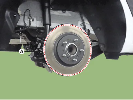
| 1. | Loosen the wheel nuts slightly. Raise the vehicle, and make sure it is securely supported. |
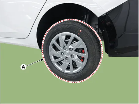
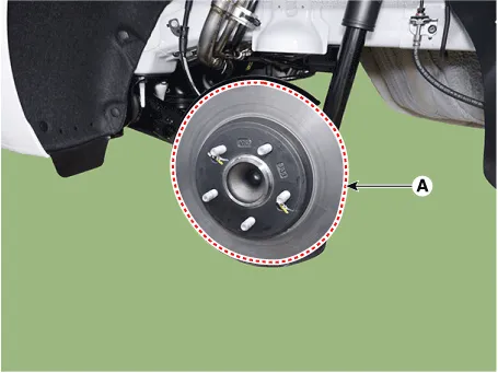
| 2. | Remove the rear wheel and tire (A) from the rear hub.
|

| 3. | Remove the rear brake caliper. (Refer to Brake System - "Rear Disc Brake") |
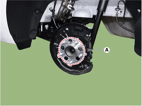
| 4. | Remove the rear brake disc (A).
|
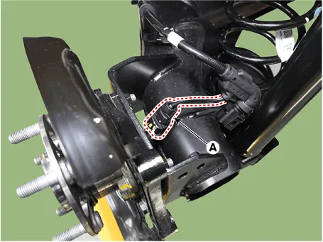
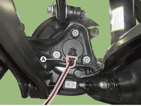
| 5. | Disconnect the rear wheel speed sensor connector (A).
|
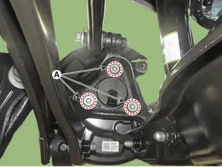
| 6. | Remove the hub bearing assembly (A) after loosening the mounting bolts.
|
| 1. | Loosen the wheel nuts slightly. Raise the vehicle, and make sure it is securely supported. |
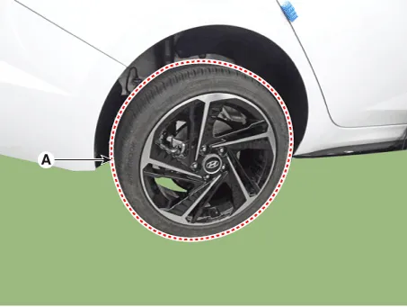
| 2. | Remove the rear wheel and tire (A) from the rear hub.
|
| 3. | Remove the rear brake caliper. (Refer to Brake System - "Rear Disc Brake") |
| 4. | Remove the rear brake disc (A) after loosening the mounting screw.
|
| 5. | Disconnect the rear wheel speed sensor connector (A).
|
| 6. | Remove the hub bearing assembly after loosening the hub bearing mounting bolts (A).
|
| 1. | Loosen the wheel nuts slightly. Raise the vehicle, and make sure it is securely supported. |
| 2. | Remove the rear wheel and tire (A) from the rear hub.
|
| 3. | Disconnect the rear wheel speed sensor connector (A).
|

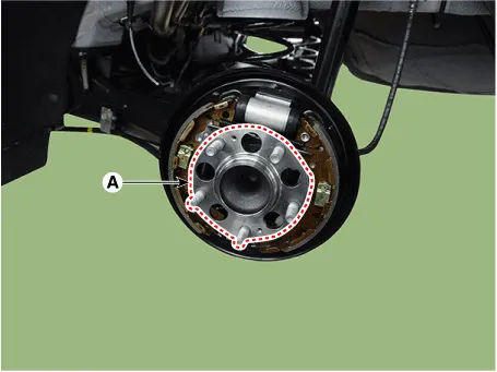
| 4. | Loosen the screw and then remove the rear drum brake (A).
|
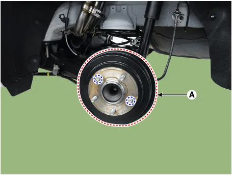
| 5. | Loosen the hub mounting bolts and then remove the hub (A) from the torsion beam.
|
| Replacement |
| 1. | Remove the rear wheel hub bearing assembly. (Refer to Driveshaft and Axle - "Rear Hub - Carrier") |
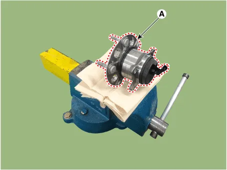
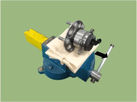
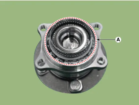
| 2. | Fix the rear hub bearing assembly (A) on the vise.
|
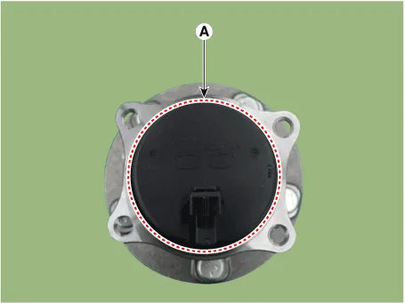
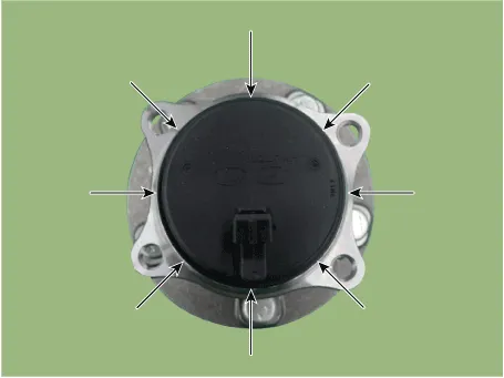
| 3. | Check the direction of the sensor cap (A).
|
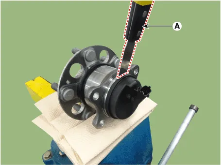
| 4. | Remove the sensor cap by hammering on a gap between sensor cap and hub bearing assembly using a scraper (A).
|
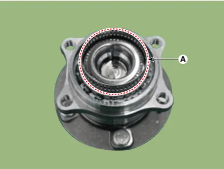
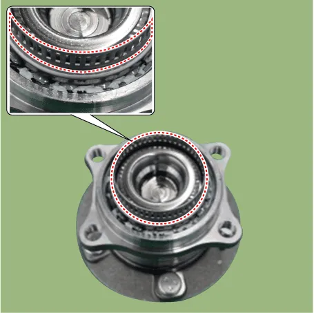
| 5. | Check if distorted or damaged the tone wheel or encoder (A).
|
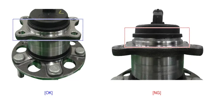
| 6. | Position the sensor cap to the same direction of sensor cap connector (A) as you checked before removing.
|
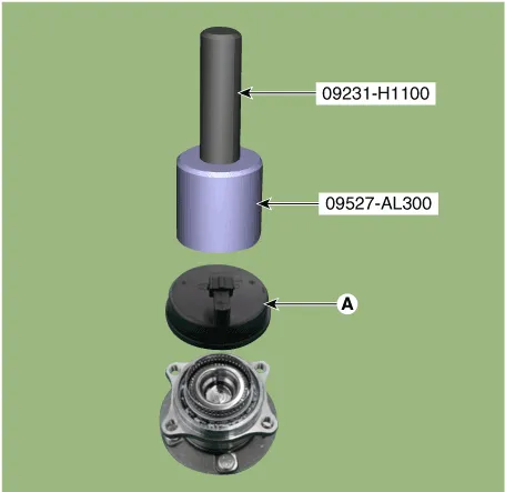
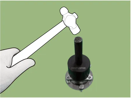
| 7. | Install the sensor cap (A) with the special service tool (09527-AL300).
|
| 8. | Install the rear wheel hub bearing assembly. (Refer to Driveshaft and Axle - "Rear Hub - Carrier") |
| Installation |
| 1. | To install, reverse the removal procedure. |
| Inspection |
| 1. | Measure the output voltage between the terminal of the wheel speed sensor and the body ground.
|
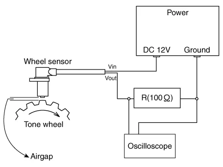
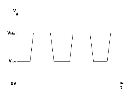
| 2. | Compare the change of the output voltage of the wheel speed sensor to the normal change of the output voltage as shown below.
|
Components and components location Components1. Front wheel speed sensor2. Front wheel speed sensor connector Repair procedures Removal1.Turn ignition switch OFF and disconnect the negative (-) battery cable.
Description and operation DescriptionIntroduction of Quick Brake Warning System (ESS)In case of quick brake by driver, the brake lamp or turn signal is blinked to warn against the vehicle at rear.
Other information:
Hyundai Elantra (CN7) 2021-2026 Service Manual: Heater & A/C Control Unit (Manual)
Components and components location Components[This illustration shows the LHD type. RHD type is symmetrical.][Connector A] Pin No Function Pin No Function 1Low (Register specifications)4Middle Low (Register specifications)2Common (Register
Hyundai Elantra (CN7) 2021-2026 Service Manual: Troubleshooting
Trouble Symptom ChartsTrouble Symptom 1Trouble Symptom 2 Trouble symptom Probable cause Remedy The set vehicle speed varies greatly upward or downward"Surging" (repeated alternating acceleration and deceleration) occurs after settingMalfunction of the vehicle speed se
Categories
- Manuals Home
- Hyundai Elantra Owners Manual
- Hyundai Elantra Service Manual
- Integrated Thermal Management Module (ITM)
- Front Bumper
- Driver assistance system
- New on site
- Most important about car
