Hyundai Elantra: Multifunction Switch / Repair procedures
Hyundai Elantra (CN7) 2021-2025 Service Manual / Body Electrical System / Multifunction Switch / Repair procedures
| Removal |
| 1. | Disconnect the negative (-) battery terminal. |
| 2. | Remove the steering wheel. (Refer to Steering System - "Steering Wheel") |
| 3. | Remove the steering column upper and lower shrouds after loosening the screws. (Refer to Body - "Steering Column Shroud Panal") |
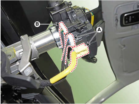
| 4. | Disconnect the multifunction switch connectors (B) and clock spring connector (A)
|
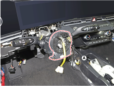
| 5. | Remove the clock spring (A).
|
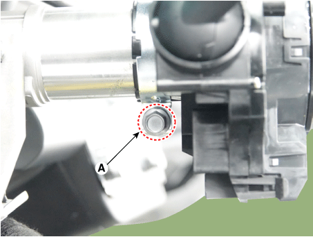
| 6. | Remove the multifunction switch assembly after loosening the clamp (A).
|
| Installation |
| 1. | Install the multifunction switch. |
| 2. | Install the clock spring. |
| 3. | Install the steering column upper and lower shrouds. |
| 4. | Install the steering wheel. |
| 5. | Connect the negative (-) battery terminal. |
| Inspection |
Multifunction Switch Inspection
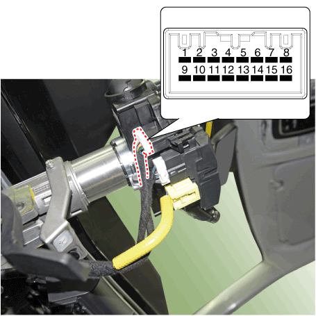
| 1. | Check for continuity between the terminals in each switch position according to the table.
[Left Handle Drive]
|
Inspection (With Diagnostic tool)
| 1. | In the body electrical system, failure can be quickly diagnosed by using the vehicle diagnostic system (Diagnostic tool). The diagnostic system (Diagnostic tool) provides the following information.
|
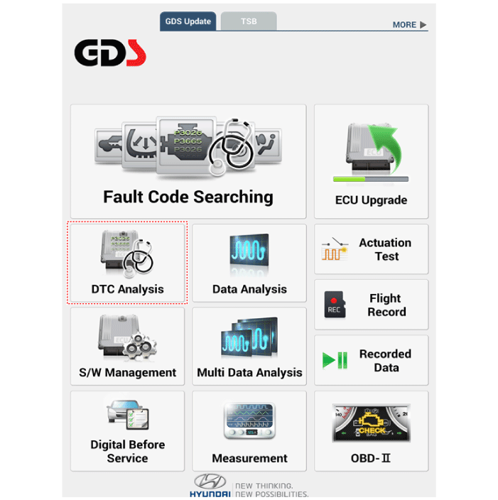
| 2. | If diagnose the vehicle by Diagnostic tool, select "DTC Analysis" and "Vehicle".
|
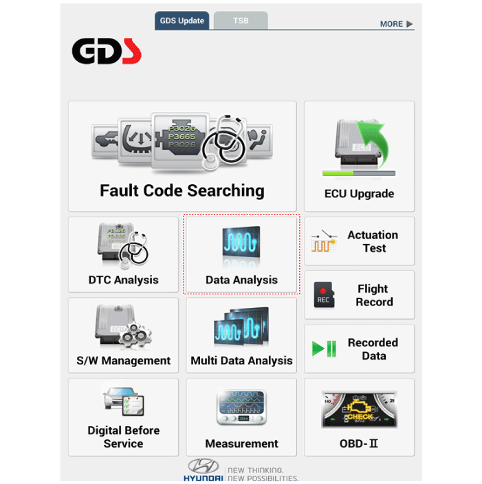
| 3. | If check current status, select the "Data Analysis" and "Car model".
|
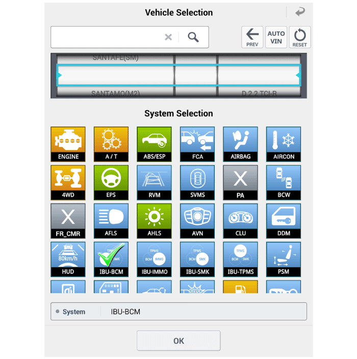
| 4. | Select the 'IBU_BCM' to search the current state of the input/output data.
|
 Specifications
S..
 Horn
Horn
..
Other information:
Hyundai Elantra (CN7) 2021-2025 Service Manual: Shift Cable
Components and components location Components1. Shift lever knob & boots assembly2. Shift lever assembly3. Shift cable4. Manual control lever5. Shift cable retainer Repair procedures Removal1.Remove the air cleaner assembly and air duct.(Refer to Engine Mechnical System - "Air cleaner")2. Remove the battery and tray.(Refer to Engine Electrical System - "Battery")3.Remove the shift ..
Hyundai Elantra (CN7) 2021-2025 Service Manual: Components and components location
Components1. Water pipe2. Water hose3. Integrated thermal management module (ITM)4. Heater pipe5. Turbo charger coolant hose6. Heater hose7. Heater pipe A8. Heater pipe A gasket9. Oil cooler hose A10. Oil cooler pipe11. Oil cooler hose B12. Water inlet fitting13. Water inlet fitting O-ring..
Copyright © 2025 www.helantra7.com

