Hyundai Elantra (CN7): Front Suspension System / Sub Frame
Repair procedures
| Removal |
[A type]
| 1. | Loosen the wheel nuts slightly. Raise the vehicle, and make sure it is securely supported. |
| 2. | Remove the front wheel and tire (A) from the front hub.
|


| 3. | Remove stabilizer bar link from the front strut after loosening the mounting nut.
|
| 4. | Remove the tie rod end ball joint by using the special service tool.
|
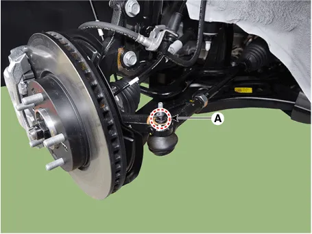
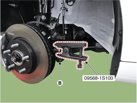
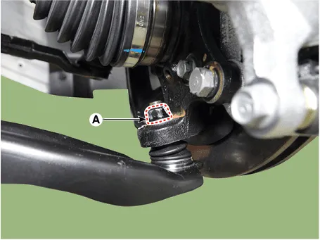
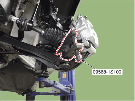
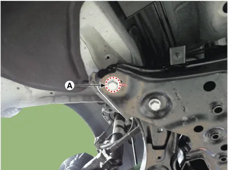
| 5. | Separate the lower arm ball joint by using the SST (09568-1S100) after loosening the lower arm mounting nut (A).
|
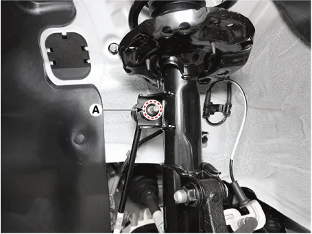
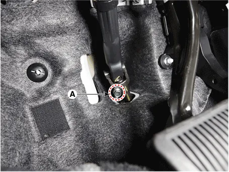
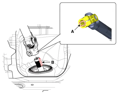
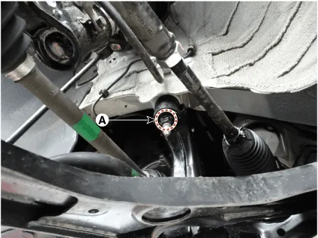
| 6. | Separate the universal joint from the steering gear box after loosening the universal joint mounting bolt (A).
|
| 7. | Remove the engine room under cover. (Refer to Engine Mechanical System - "Engine Room Under Cover") |
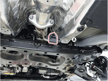
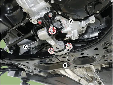
| 8. | Remove the muffler rubber hanger (A).
|
| 9. | Remove the roll rod bracket (C) after loosening the mounting bolts (A, B).
|
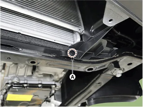
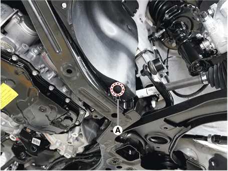
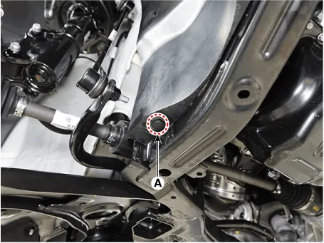
| 10. | Remove the fastener (A). [LH]
[RH]
|
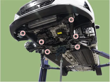
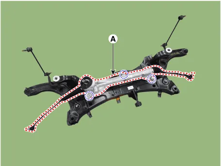
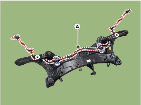
| 11. | Remove the sub frame after loosening the mounting bolts and nuts.
|

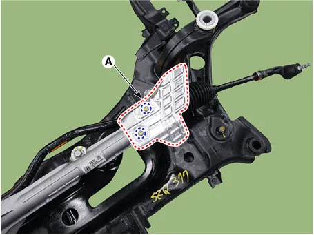
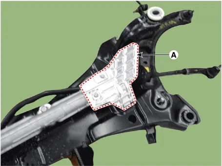
| 12. | Remove the heat protector (A).
|
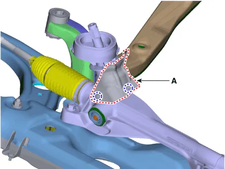
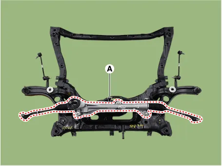
| 13. | Remove the steering gear box (A) from the sub frame after loosening the mounting bolts.
|
| 14. | Remove the stabilizer bar (A) from the sub frame after loosening the mounting bolts.
|
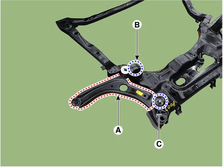
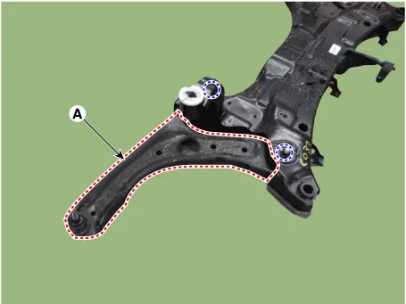
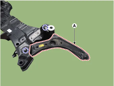
| 15. | Remove the front lower arm (A) from the sub frame.
[LH]
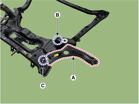
[RH]
|
[B type]
| 1. | Loosen the wheel nuts slightly. Raise the vehicle, and make sure it is securely supported. |
| 2. | Remove the front wheel and tire (A) from the front hub.
|
| 3. | Remove stabilizer bar link from the front strut after loosening the mounting nut.
|
| 4. | Remove the tie rod end ball joint by using the special service tool.
|
| 5. | Separate the lower arm ball joint by using the SST (09568-1S100) after loosening the lower arm mounting nut (A).
|
| 6. | Separate the universal joint from the steering gear box after loosening the universal joint mounting bolt.
|
| 7. | Remove the engine room under cover. (Refer to Engine Mechanical System - "Engine Room Under Cover") |
| 8. | Remove the muffler rubber hanger (A).
|
| 9. | Remove the roll rod bracket (C) after loosening the mounting bolts (A, B).
|
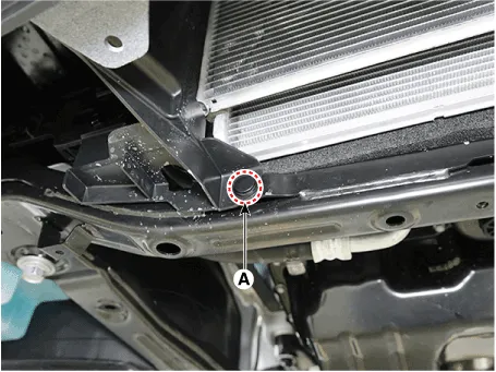
| 10. | Remove the subframe by loosening the mounting bolts (A) and nuts (B).
|
| 11. | Remove the heat protector (A).
|
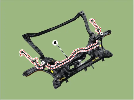
| 12. | Remove the steering gear box (A) after loosening the mounting bolts.
|
| 13. | Remove the stabilizer bar (A) after loosening the mounting bolts.
|
| 14. | Remove the front lower arm (A) from the sub frame.
[LH]
[RH]
|
| Installation |
| 1. | To install, reverse the removal procedures. |
| 2. | Check the alignment. (Refer to Suspension System - "Alingment") |
Repair procedures Removal1.Loosen the wheel nuts slightly.Raise the vehicle, and make sure it is securely supported.2.Remove the front wheel and tire (A) from the front hub.
Other information:
Hyundai Elantra (CN7) 2021-2026 Service Manual: Components and components location
C
Hyundai Elantra (CN7) 2021-2026 Service Manual: Warning Indicator
Components and components location Components1. BSD Indicator2. Side repeater lamp Repair procedures Inspection1.Disconnect the negative (-) battery terminal.2.Remove the front door trim.(Refer to Body - "Front door trim")3.Disconnect the power door mirror connector from the harness4.
Categories
- Manuals Home
- Hyundai Elantra Owners Manual
- Hyundai Elantra Service Manual
- Body Electrical System
- Engine Mechanical System
- Engine Control / Fuel System
- New on site
- Most important about car

Copyright © 2026 www.helantra7.com - 0.0282