
Hyundai Elantra (CN7): Keyless Entry And Burglar Alarm / Repair procedures
| Inspection |
|

| 1. | Remove the front door trim. (Refer to Body - "Front Door Trim") |
| 2. | Remove the front door module. (Refer to Body - "Front Door Module") |
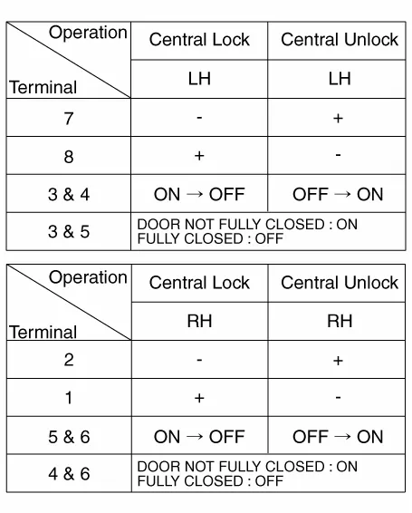
| 3. | Disconnect the connector from the actuator.
| |||||||||||||||||||||||||||||
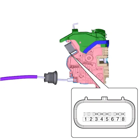
| 4. | Check actuator operation by connecting power and ground according to the table. To prevent damage to the actuator, apply battery voltage only momentarily.
|
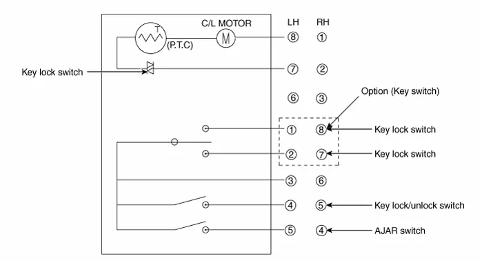
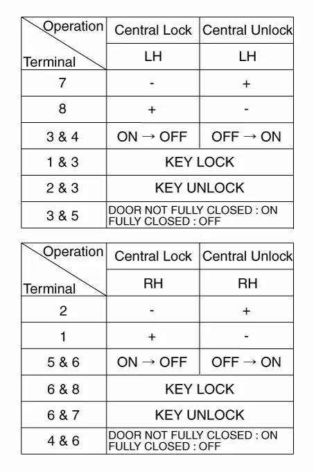
| 1. | Remove the rear door trim. (Refer to Body - "Rear Door Trim") |
| 2. | Remove the rear door module. (Refer to Body - "Rear Door Module") |
| 3. | Disconnect the connectors from the actuator.
| |||||||||||||||||||||||||||||
| 4. | Check actuator operation by connecting power and ground according to the table. To prevent damage to the actuator, apply battery voltage only momentarily.
|
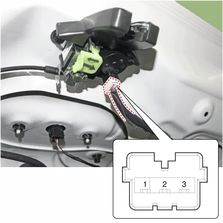
| 1. | Remove the trunk lid trim. (Refer to Body - "Trunk Lid Trim") |
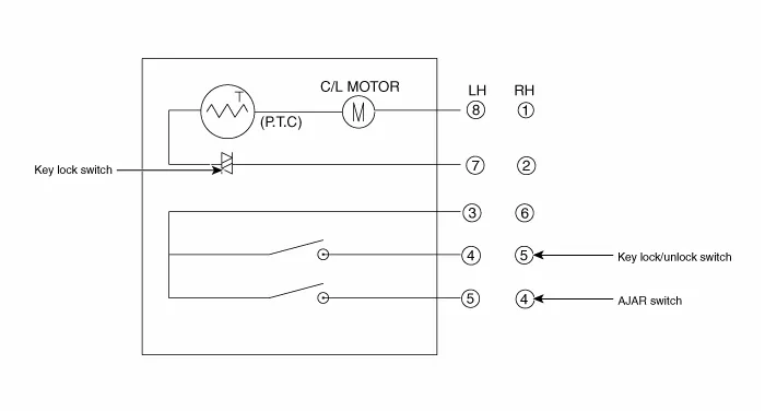
| 2. | Disconnect the connector from the actuator
|
| 3. | Check actuator operation by connecting power and ground according to the table. To prevent damage to the actuator, apply battery voltage only momentarily.
|
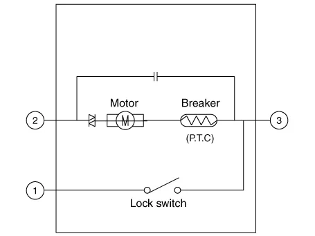

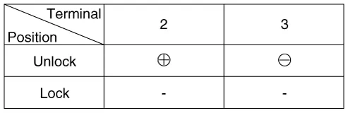
| 4. | Checking the trunk of the vehicle power option power refers to the trunk module. |
| 1. | Disconnect the connector (A).
|
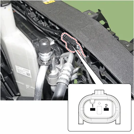
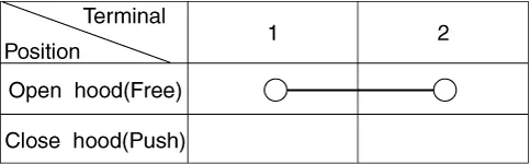
| 2. | Check for continuity between the terminals and ground according to the table (Refer to Body - "Hood Latch")
|
Specification Item Specification Power source3VOperating temperature-10°C ~ +60°CRF ModulationFSKLF ModulationASKRF frequency433.
Other information:
Hyundai Elantra (CN7) 2021-2026 Service Manual: Repair procedures
Diagnosis with Diagnostic tool1.In the body electrical system, failure can be quickly diagnosed by using the vehicle diagnostic system (Diagnostic tool).The diagnostic system (Diagnostic tool) provides the following information.(1)Fault Code Searching : Checking failure and code number (DTC)(2)Data Analysis : Checking the system input/output data s
Hyundai Elantra (CN7) 2021-2026 Service Manual: Wireless Power Charging Unit
Components and positions Components Circuit diagram Circuit Diagram Repair procedures Removal • Handling wireless charging system parts by wet hands may cause electric shock. 1.Disconnect the negative (-) battery terminal.
Categories
- Manuals Home
- Hyundai Elantra Owners Manual
- Hyundai Elantra Service Manual
- Driver assistance system
- Engine Control / Fuel System
- Drive Mode
- New on site
- Most important about car
