Hyundai Elantra: Dual Clutch Transmission Control System / Input Speed Sensor
Description and operation
| Description |
| • |
Components location : DCT (Dual Clutch Transmission)
|
| • |
Function
The input shaft speed sensor is important in that it detects the input shaft RPM and sends this information to the Transmission Control Module (TCM). It provides important input information for electric control. The information is needed in all operations, including feedback control, gear shift control and failure detection of other sensors. |
Specifications
| Specification |
|
Item
|
Specification
|
| Type | Hall effect sensor |
| Output signal | High: 11.8 - 16.8 mA |
| Low: 5.9 - 8.4 mA |
Schematic diagrams
| Circuit Diagram |
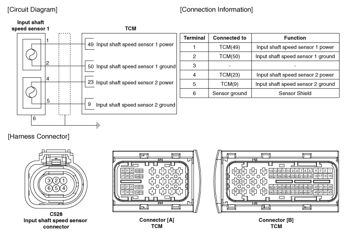
Components and components location
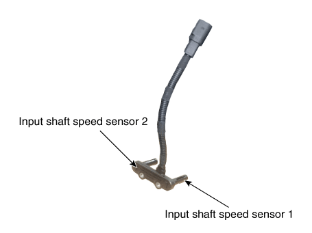
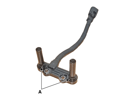
| Components |
| 1. Input shaft speed sensor 1 (Odd) | 2. Input shaft speed sensor 2 (Even) |
Repair procedures
| Inspection |
| 1. | The DCT system can be more quickly diagnosed for troubles by using the vehicle diagnostic system (diagnostic tool). (Refer to DTC guide) diagnostic tool provides the following information.
|
| Removal |
| 1. | Turn ignition switch OFF and disconnect the battery negative (-) terminal. |
| 2. | Remove the air cleaner assembly and air duct. (Refer to Engine Mechnical System - "Air cleaner") |
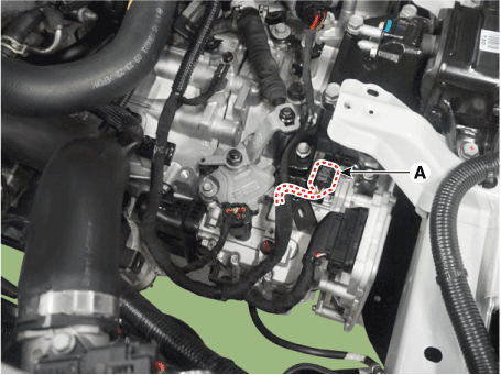
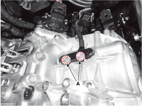
| 3. | Disconnect the input shaft speed sensor connector (A).
|
| 4. | Remove the clutch actuator. (Refer to Dual Clutch Transmission Control System - "Clutch Actuator & TCM Assembly") |
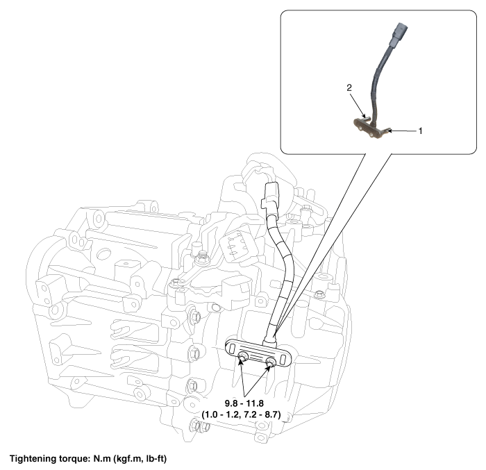
| 5. | Remove the input shaft speed sensor (A).
|
| Installation |
| 1. | Install in the reverse order of removal.
|

 Gear Actuator Assembly
Description and operation
Description•
Gear actuator uses signals from TCM to control the gear.
Specifications
Specification
Item
Specification
Operation condition-40 to 257 °F (- 40 to 125 °C )Rated voltage12V
Components and components location
Components1...
 Inhibitor Switch
Description and operation
Description•
The inhibitor switch is installed on top of transmission, and is connected to the shift lever through shift cable...
Other information:
Hyundai Elantra (CN7) 2021-2025 Owner's Manual: Fuse/Relay Panel Description
Instrument panel fuse panel Inside the fuse/relay box cover, you can find the fuse/relay label describing fuse/ relay names and ratings. Information Not all fuse panel descriptions in this manual may be applicable to your vehicle; the information is accurate at the time of printing...
Hyundai Elantra (CN7) 2021-2025 Service Manual: Smart Key Diagnostic
Repair procedures InspectionSelf Diagnosis With Scan ToolIt will be able to diagnose defects of SMART KEY system with Diagnostic tool quickly. Diagnostic tool can operates actuator forcefully, input/output value monitoring and self diagnosis.The following three features will be major problem in SMART KEY system...
Categories
- Manuals Home
- 7th Gen Hyundai Elantra Owners Manual
- 7nd Gen Hyundai Elantra Service Manual
- Integrated Thermal Management Module (ITM)
- Rear Seats
- System disabled
- Engine Oil
- Interior Overview
Rear center seat belt
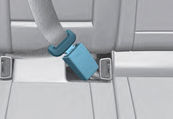
When using the rear center seat belt, the buckle with the “CENTER” mark must be used.
WARNING
Make sure that the seatback is locked in place when using the rear center seat belt.
If not, the seatback may move when there is a sudden stop or collision, which could result in serious injury.

Copyright © 2025 www.helantra7.com