Hyundai Elantra (CN7): Roof Trim / Roof Trim Assembly
Components and components location
| Component Location |

| 1. Roof Trim Assembly |
Repair procedures
| Replacement |
|

|

| 1. | Remove the front seat assembly. (Refer to Front Seat - "Front Seat Assembly") |
| 2. | Remove the rear seat assembly. (Refer to Rear Seat - "Rear Seat Assembly") |
| 3. | Remove the front pillar trim. (Rear to Interior Trim - "Front Pillar Trim") |
| 4. | Remove the canter pillar upper trim. (Rear to Interior Trim - "Center Pillar Trim") |
| 5. | Remove the rear pillar trim. (Rear to Interior Trim - "Rear Pillar Trim") |
| 6. | Remove the sunvisor and retainer. (Rear to Roof Trim - "Sunvisor") |
| 7. | Remove the assist handle. (Rear to Roof Trim - "Assist Handle") |
| 8. | Remove the overhead console lamp. (Rear to Body Electrical System - "Overhead Console Lamp") |
| 9. | Remove the room lamp. (Rear to Body Electrical System - "Room Lamp") |
| 10. | Disconnect the rear view mirror connector. (Refer to Body Electrical System - "Electro Chromic Inside Rear View Mirror") |
| 11. | Disconnect the rain sensor connector. (Refer to Body Electrical System - "Rain Sensor") |
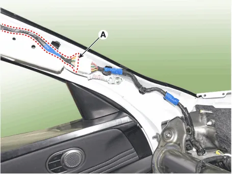
| 12. | Disconnect the roof trim main connector (A) and the mounting clips in the front pillar. [LH]
[RH]
|

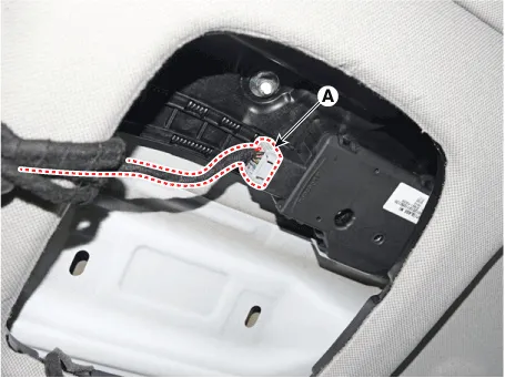
| 13. | Disconnect the sunroof motor connector (A).
|
| 14. | Remove the rear window galss. (Refer to "Windshield Glass") |
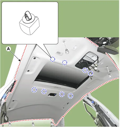
| 15. | Remove the roof trim mounting clip and remove the roof trim assembly (A).
|
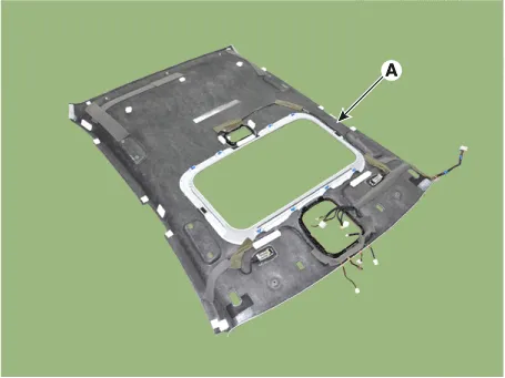
| 16. | Remove roof trim wiring harness (A) from the roof trim.
|

| 17. | To install, reverse the removal procedure.
|
Components and components location Component Location 1. Assist handle Repair procedures Replacement • When removing with a flat-tip screwdriver or remover, wrap protective tape around the tools to prevent damage to components.
Other information:
Hyundai Elantra (CN7) 2021-2025 Service Manual: Troubleshooting
TroubleshootingDiagnosis with Diagnostic tool1.In the body electrical system, failure can be quickly diagnosed by using the vehicle diagnostic system (Diagnostic tool).The diagnostic system (Diagnostic tool) provides the following information.1)Fault Code Searching : Checking failure and code number (DTC)2)Data Analysis : Checking the system input/
Hyundai Elantra (CN7) 2021-2025 Service Manual: ADAS Parking ECU (ADAS_PRK)
Components and components location Components and Components Location Repair procedures Removal • Use a plastic panel removal tool to remove interior trim pieces without marring the surface.• Take care not to bend or scratch the trim and panels.
Categories
- Manuals Home
- Hyundai Elantra Owners Manual
- Hyundai Elantra Service Manual
- Maintenance
- Body Electrical System
- Rear Seats
- New on site
- Most important about car
