Hyundai Elantra: Crash Pad / Cowl Cross Bar Assembly
Hyundai Elantra (CN7) 2021-2025 Service Manual / Body (Interior and Exterior) / Crash Pad / Cowl Cross Bar Assembly
Components and components location
| Component Location |
| [This illustration shows the LHD type. RHD type is symmetrical.] |
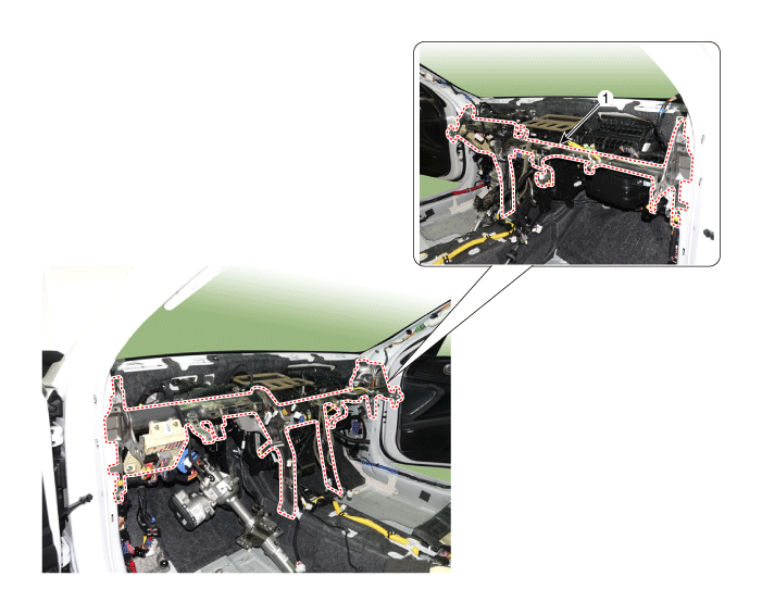
| 1. Cowl cross bar assembly |
Repair procedures
| Replacement |
|
|
| 1. | Disconnect the negative ( - ) battery terminal. |
| 2. | Recover the refrigerant with a recovery/recycling/charging station. |
| 3. | When the engine is cool, drain the engine coolant from the radiator. (Refer to Engine Mechanical System - “Coolant”) |
| 4. | Remove the cowl top cover. (Refer to "Cowl Top Cover") |
| 5. | Remove the front door scuff trim. (Refer to Interior Trim - "Front Door Scuff Trim") |
| 6. | Remove the hood latch release handle. (Refer to hood -"Hood Latch Release Handle") |
| 7. | Remove the cowl side trim. (Refer to Interior Trim - "Cowl Side Trim") |
| 8. | Remove the battery. (Refer to Engine Electrical System - "Battery") |
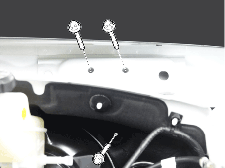
| 9. | Loosen the cowl cross member mounting bolts.
|
| 10. | Remove both sides of front seat assembly. (Refer to Front Seat - "Front Seat Assembly") |
| 11. | Remove the main crash pad assembly. (Refer to Crash Pad - "Main Crash Pad Assembly") |
| 12. | Disconnect the steering column connectors. (Refer to Steering System - "Steering Column and Shaft") |
| 13. | Loosen the mounting nuts and through bolts in the frontal area and lower the steering column. (Refer to Steering System - "Steering Column and Shaft") |
| 14. | Remove the shift lever assembly. (Refer to Manual Transaxle System - "Shift lever") (Refer to Automatic Transaxle System - "Shift lever") |
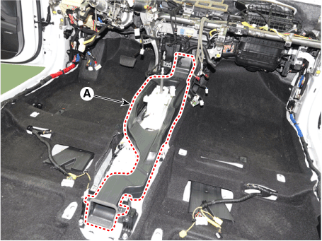
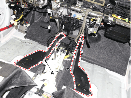
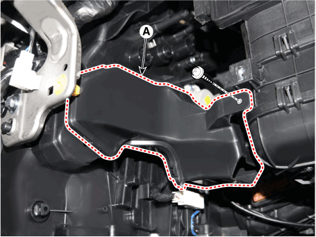
| 15. | Loosen the mounting nut and remove the center console duct (A).
|
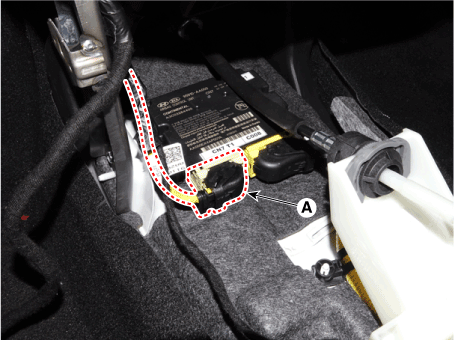
| 16. | Disconnect the airbag control module (SRSCM) connector (A).
|
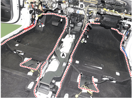
| 17. | Remove the rear air duct (A) and remove the floor carpet (B) from the rear.
|
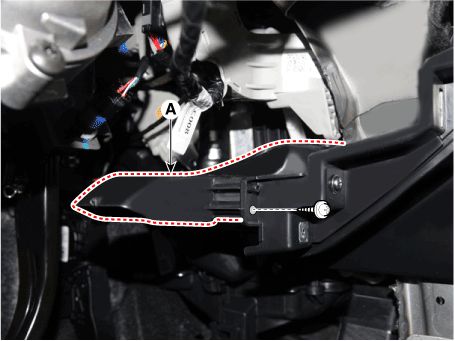
| 18. | Remove the rear air duct (A).
|
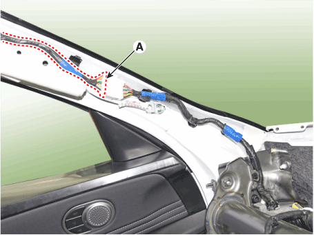
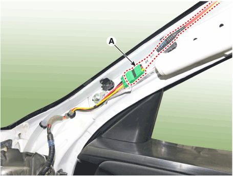
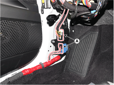
| 19. | Detach the various connector of front pillar (A).
|
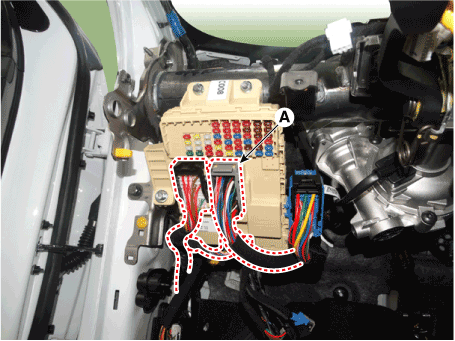
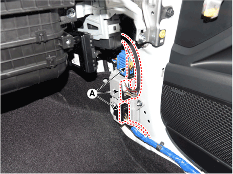
| 20. | Disconnect the junction box connectors (A).
|
| 21. | Disconnect the multi box connectors (A).
|
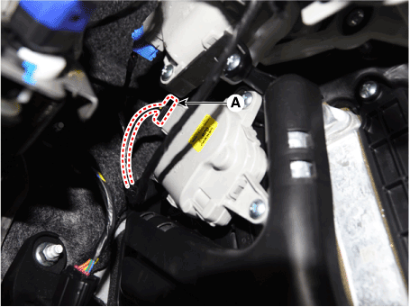
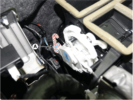
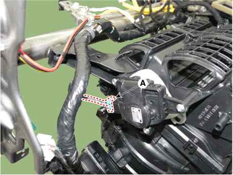
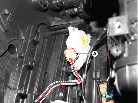
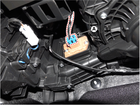
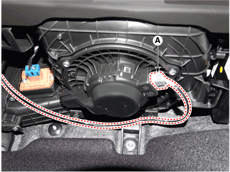
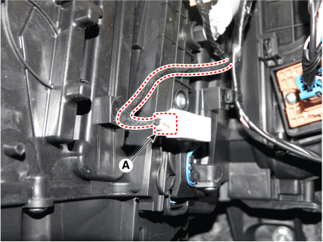
| 22. | Disconnect the heater & blower unit connectors.
|
| 23. | Remove the integrated body control unit (IBU). (Refer to Body Electrical System - "Integrated Body control Unit (IBU)" |
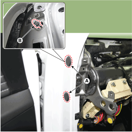
| 24. | Loosening the cowl cross bar side mounting bolt (B) after loosening the plug hole (A).
|
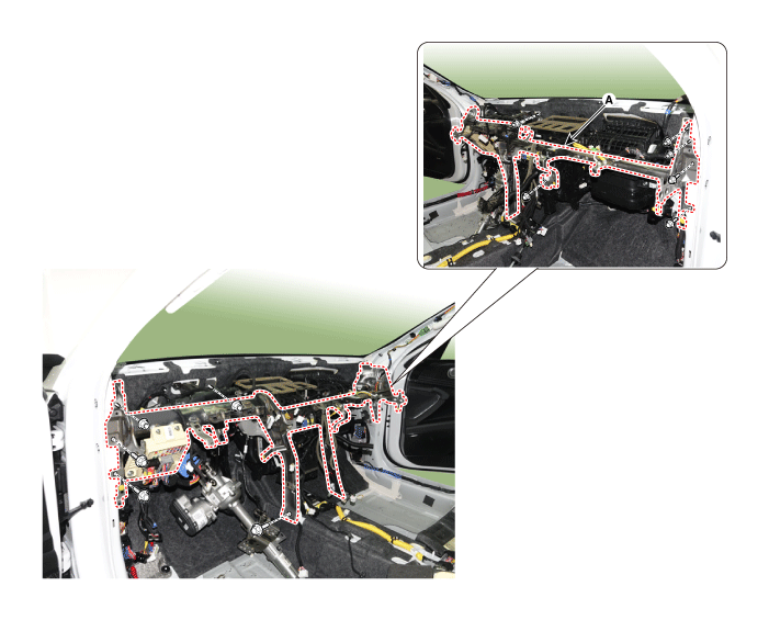
| 25. | Loosen the mounting bolts, remove the cowl crossbar assembly (A).
|
| 26. | Install in the reverse order of removal.
|
 Main Crash Pad Assembly
Components and components location
Component Location [This illustration shows the LHD type. RHD type is symmetrical.]1. Main crash pad assembly
Repair procedures
Replacement
•
When removing with a flat - tip screwdriver or remover, wrap protective tape around the tools to prevent damage to components...
 Roof Trim
..
Other information:
Hyundai Elantra (CN7) 2021-2025 Service Manual: Components and components location
Components Location1. Fuel Tank 2. Fuel Pump3. Fuel Fiter4. Fuel Pressure Regulator5. Canister6. Fuel tank air filter7. Fuel pump plate cover8. Fuel filler hose9. Vapor hose10. Ventilation hose11. Leveling hose..
Hyundai Elantra (CN7) 2021-2025 Owner's Manual: Defroster
NOTICE To prevent damage to the conductors bonded to the inside surface of the rear window, never use sharp instruments or window cleaners containing abrasives to clean the window. Information If you want to defrost and defog the front windshield, refer to “Windshield Defrosting and Defogging” in this chapter. Rear window defroster The defroster heats the window to remove frost, fog an..
Copyright © 2025 www.helantra7.com


