Hyundai Elantra: Crash Pad / Main Crash Pad Assembly
Hyundai Elantra (CN7) 2021-2025 Service Manual / Body (Interior and Exterior) / Crash Pad / Main Crash Pad Assembly
Components and components location
| Component Location |
| [This illustration shows the LHD type. RHD type is symmetrical.] |
| 1. Main crash pad assembly |
Repair procedures
| Replacement |
|

|

| 1. | Disconnect the negative ( - ) battery terminal. |
| 2. | Remove the floor console assembly. (Refer to Floor Console - "Floor Console Assembly") |
| 3. | Remove the front pillar trim.
|

| 4. | Detach the clips, then remove the front door body side weatherstrip (A). [LH]
[RH]
|
| 5. | Using a screwdriver or remover, remove the crash pad side cover (A). [LH]
[RH]
|

| 6. | Loosen the mounting screws, remove the crash pad lower panel (A).
|
| 7. | Press the lock pin, separate diagnosis connector (A).
|
| 8. | Using a screwdriver or remover, remove the photo sensor cover (A).
|
| 9. | Press the lock pin, separate the connectors (A).
|
| 10. | Using a screwdriver or remover, remove the cluster fascia panel upper garnish (A).
|
| 11. | Remove the crash pad garnish [LH]
[RH]
|

| 12. | Loosen the mounting screws by turning the steering wheel to the left and right, and remove the steering column shroud lower panel (A).
|
| 13. | Remove the instrument cluster. (Refer to Body Electrical System - "Instrument Cluster") |
| 14. | Loosen the mounting screw, remove the center speaker (A).
|
| 15. | Press the lock pin, separate the center speaker connector (A).
|
| 16. | Remove the glove box housing cover. (Refer to Crash Pad - "Glove Box Housing Cover") |
| 17. | Loosen the mounting screws, remove the A/C & heater controller unit (A).
|
| 18. | Disconnect the A/C & heater controller connectors (A) and hose (B).
|
| 19. | Loosen the mounting screws, remove the AVN keyboard assembly (A).
|
| 20. | Press the lock pin, separate the start button connector (A).
|
| 21. | Press the lock pin, separate the connectors (A).
|
| 22. | Remove the USB port assembly (A) by pulling it in the direction of the arrow.
|
| 23. | Press the lock pin, separate the connectors (A).
|
| 24. | Loosen the mounting screws, remove the crash pad center panel (A).
|
| 25. | Remove the steering wheel. (Refer to Steering System - "Steering Wheel") |
| 26. | Remove the multifunction switch assembly. (Refer to Body Electrical System - "Multifunction Switch") |
| 27. | Remove the crash pad air vent. [LH]
[RH]
|
| 28. | Loosen the passenger's airbag (PAB) mounting nuts (A).
|
| 29. | Loosen the mounting bolts and nuts and remove the main crash pad assembly (A).
|
| 30. | Press the lock pin, separate the passenger's airbag (PAB) connectors (A).
|
| 31. | To install, reverse the removal procedure.
|
 Crash Pad Center Panel
Components and components location
Component Location [This illustration shows the LHD type. RHD type is symmetrical.]1. Crash pad center panel
Repair procedures
Replacement
•
When removing with a flat - tip screwdriver or remover, wrap protective tape around the tools to prevent damage to components...
 Cowl Cross Bar Assembly
Components and components location
Component Location [This illustration shows the LHD type. RHD type is symmetrical.]1. Cowl cross bar assembly
Repair procedures
Replacement
•
When removing with a flat - tip screwdriver or remover, wrap protective tape around the tools to prevent damage to components...
Other information:
Hyundai Elantra (CN7) 2021-2025 Service Manual: Components and components location
Component Location1. Smart key unit (IBU)2. Interior antenna 23. outside door handle4. Interior antenna 15. FOB Key6. Door antenna1. Bumper antenna2. Trunk antenna..
Hyundai Elantra (CN7) 2021-2025 Owner's Manual: Function operation
Basic function Function warning and control The basic feature of Forward Collision- Avoidance Assist is to help warn and control the vehicle depending on collision level: ‘Collision Warning’, ‘Emergency Braking’ and ‘Stopping vehicle and ending brake control ’. Collision warning To warn the driver of a collision, the ‘Collision Warning’ warning message will appear on th..
Categories
- Manuals Home
- 7th Gen Hyundai Elantra Owners Manual
- 7nd Gen Hyundai Elantra Service Manual
- Control Cable
- System disabled
- Engine Mechanical System
- Maintenance
- Engine Oil
Tachometer
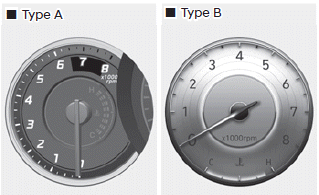
The tachometer indicates the approximate number of engine revolutions per minute (RPM).
Use the tachometer to select the correct shift points and to prevent lugging and/ or over-revving the engine.
NOTICE
Do not operate the engine within the tachometer's RED ZONE. This may cause severe engine damage.

Copyright © 2025 www.helantra7.com